
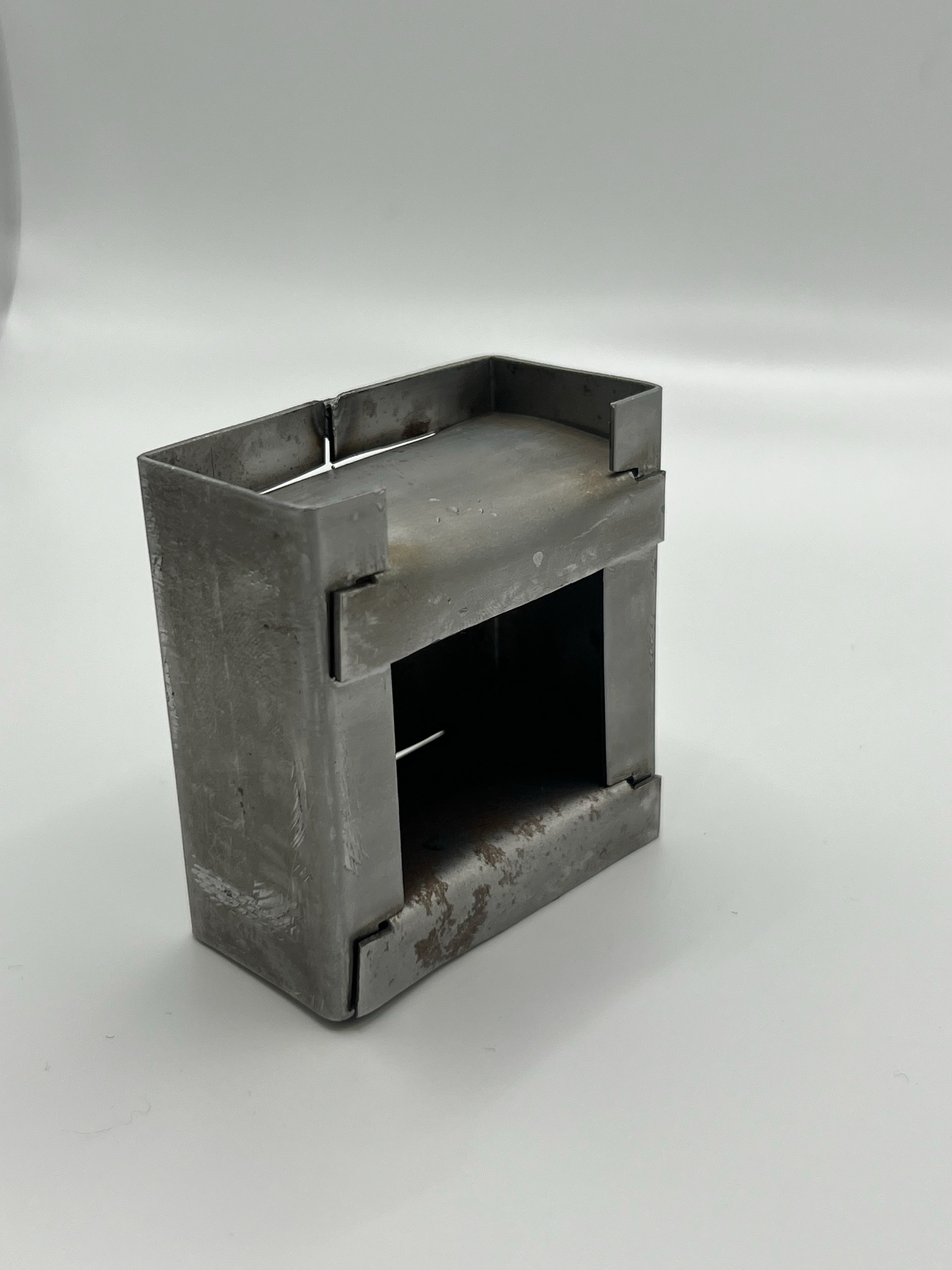
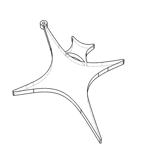
After months of sampling and no real idea of which direction to take, I finally found an idea that I wanted to develop further. This was my first sample of testing the slot mechanism that I had been researching and sampling early in this project. I had an idea to create a set of side tables. This came to me when I had finished my coffee table sample for Great Northern. I had the idea to create a set of tables, all using the slot and fold joints. I wanted to have a 3-piece set consisting of 2 side tables and one coffee table unit. The reason I didn't stick primarily with my coffee table design was that it was too simplistic and not complex enough. The simple cross-slotting base had been done so much so I needed to take the connection in a different manner and this was the first sample and design idea I came up with.
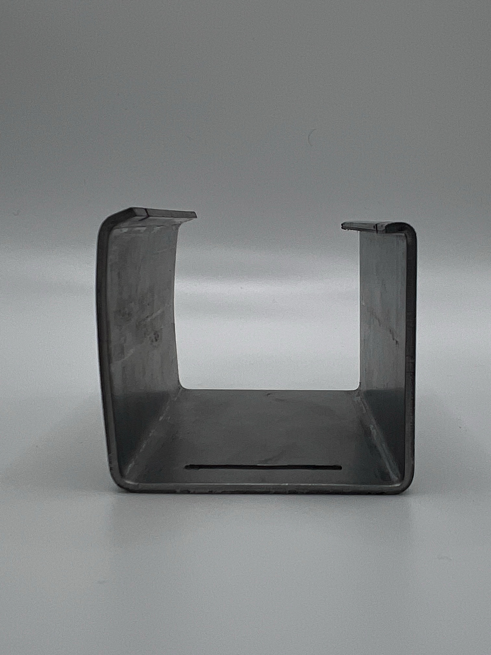
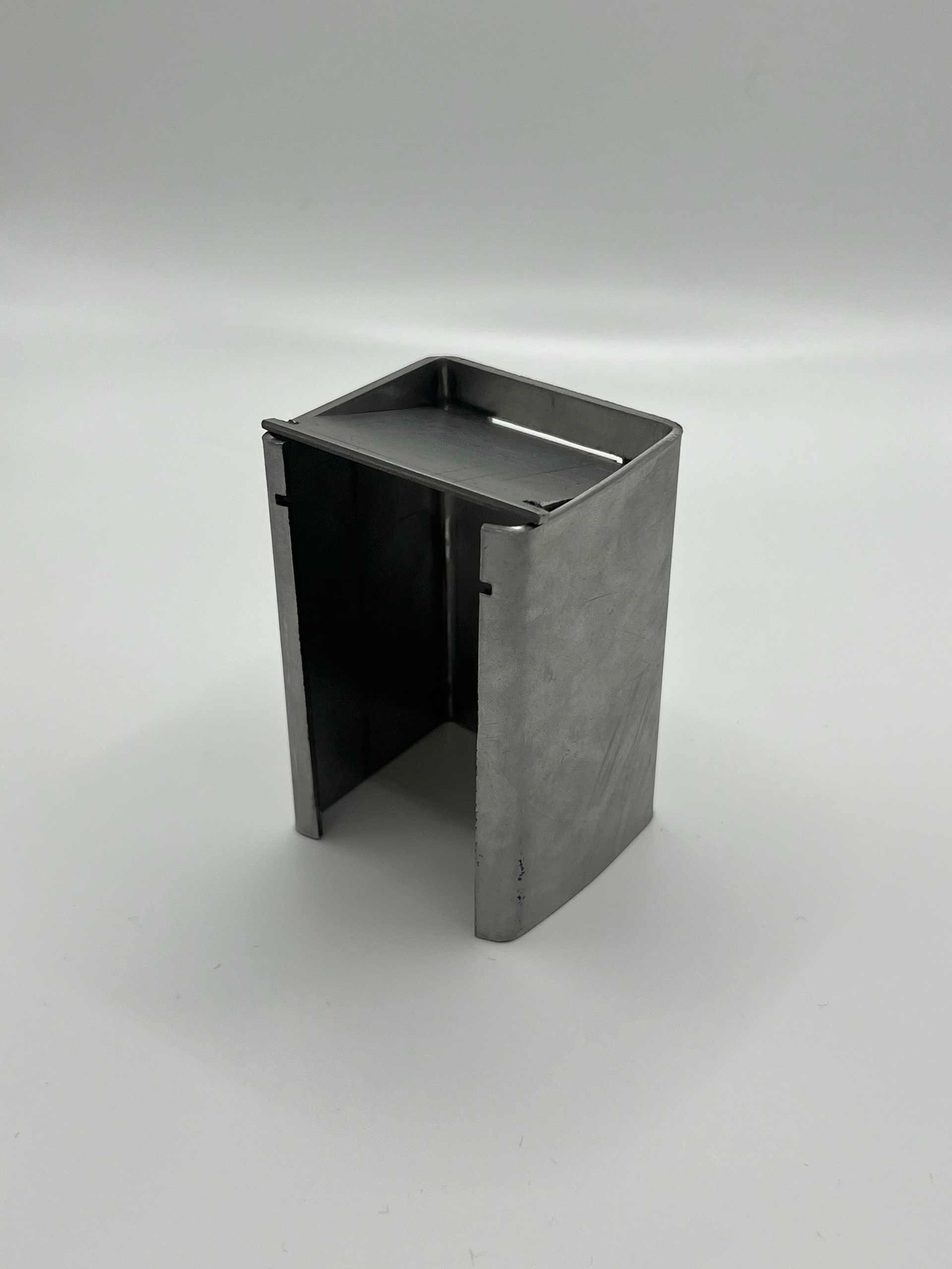
This sample was made with 3 mm thick steel, which was far too thick for a small maquette sample. Despite it not coming together, it still opened up this idea more and allowed me to envision this idea further.
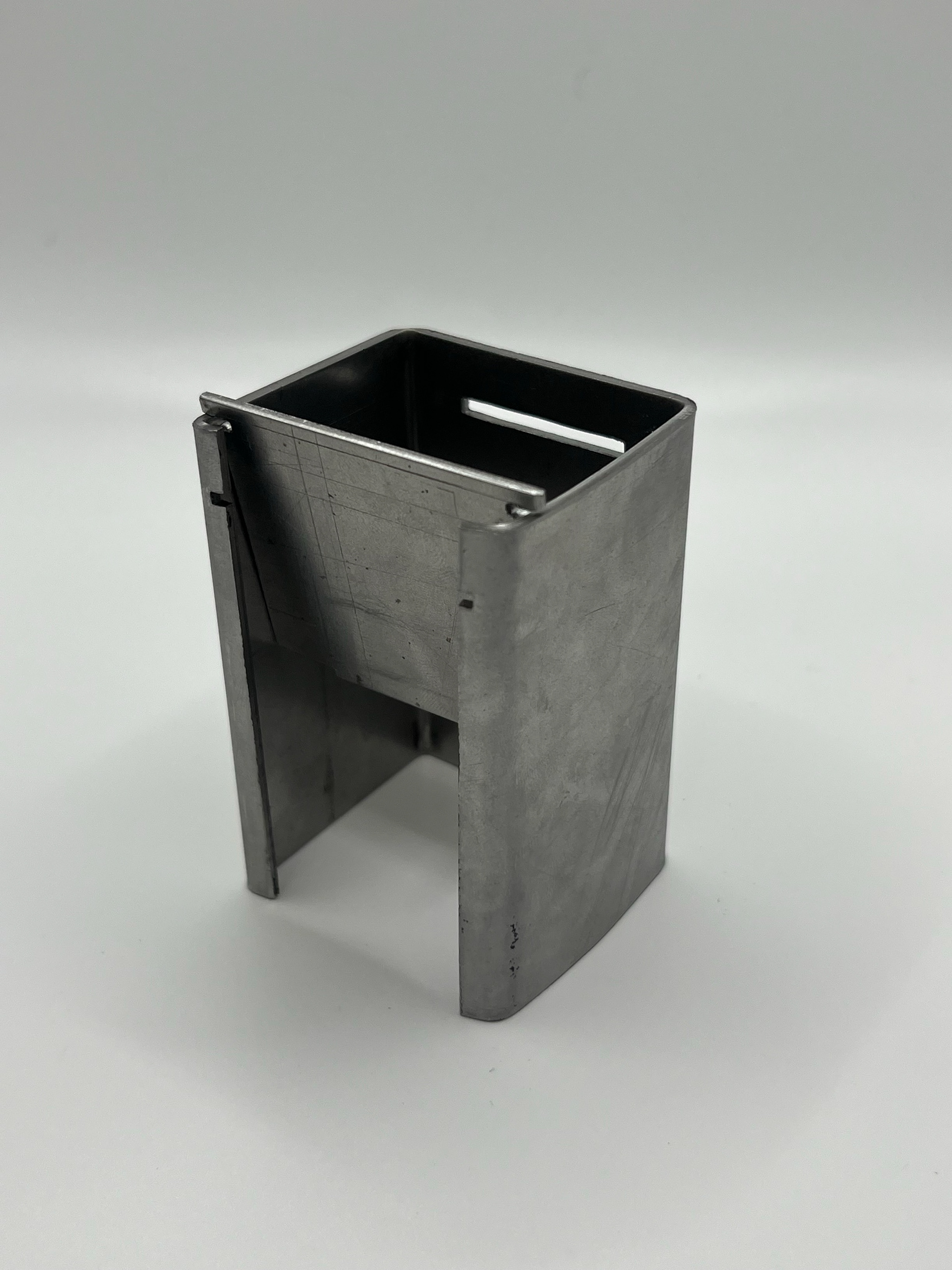
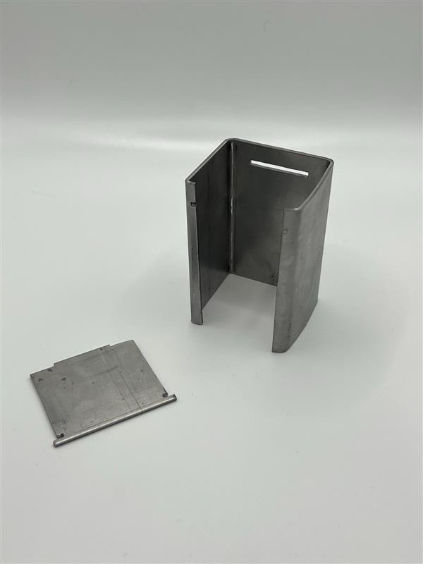
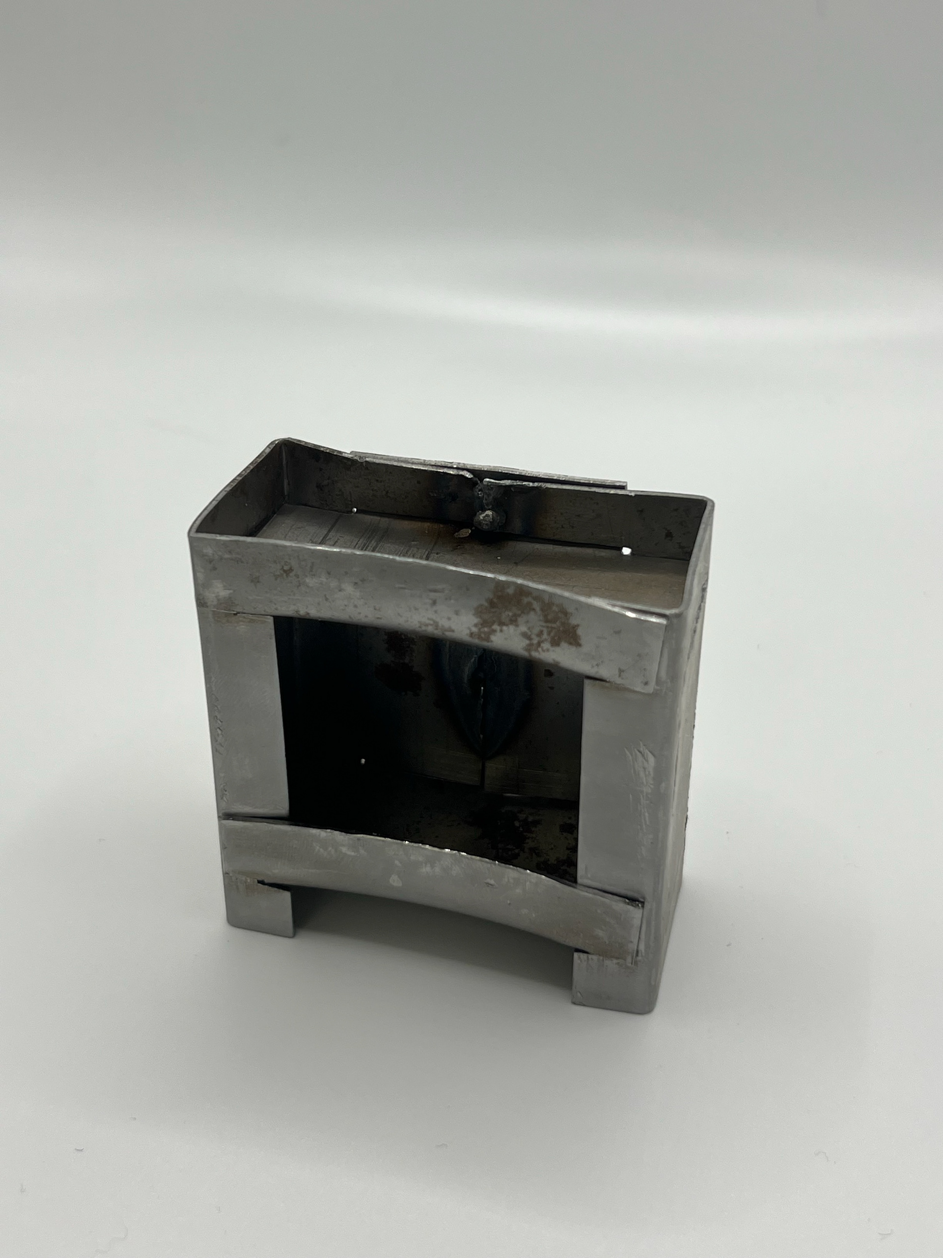
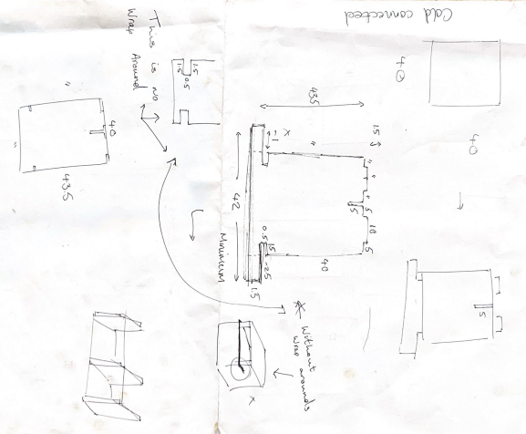
I continued to develop this idea and looked at how I could lock the shelves onto the opposing axis to the back and sides of this form. To do this, I took the access from bends off the back and sides, which you can see in the first sample. I then gave the shelf extra points on the front face to bend around the side panels. This didn't look very aesthetically nice; however, it served the function well to hold the shelf in place alongside the tab on the back. I then found that the shelf would fall forward went it was leant forward. This led me to add the gold pin in the back to lock it once again.
I found this sample stuck out too much at the back. As its intended form was to be sofa side tables, this design needed altering so it could sit flush against a wall. I also used 3 mm thick steel for this, which was just too thick for the scale of these samples.
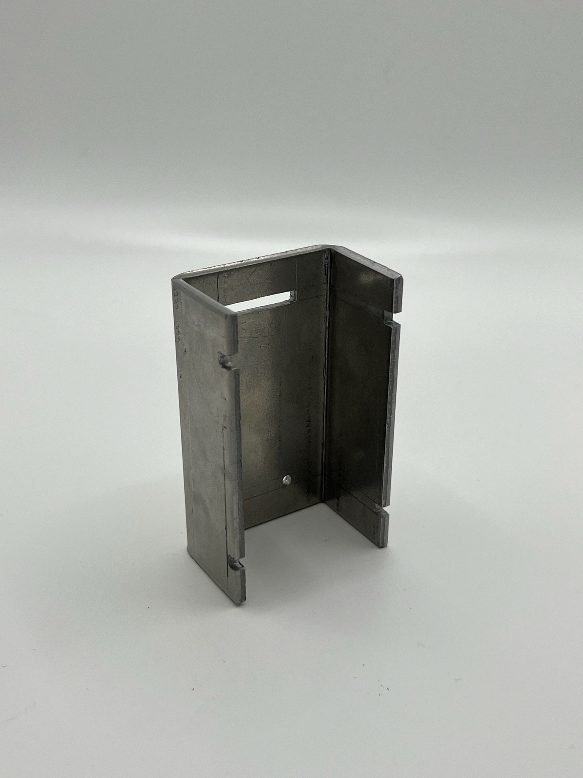
I moved on to the next sample, which you can see below. I used folds to create a locking mechanism, but to get the shelves in, I had to cut the back and side panels down the centre, which seemed to work, but it required me to weld them back together.
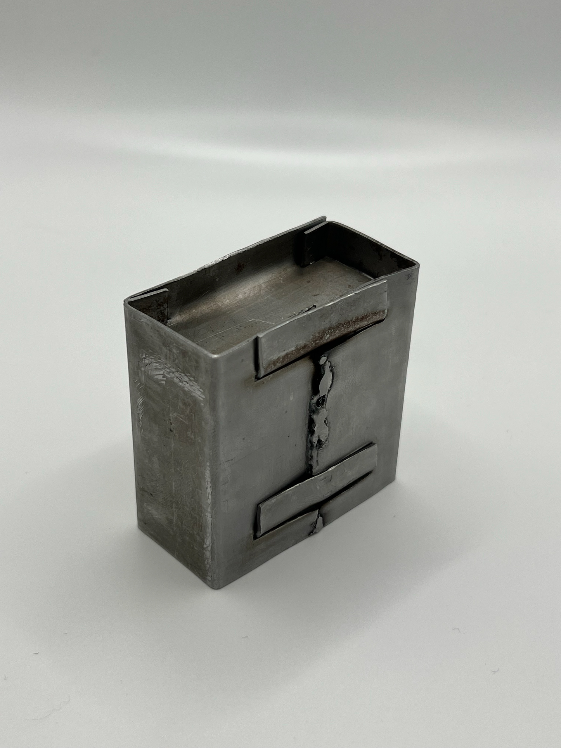
This gave me a good idea to make the back and side panels 2 separate components that meet in the middle. This would allow for the components to come together a lot easier and allow me to design the templates for the shelf, knowing they could fold at the front and back using this tab design.
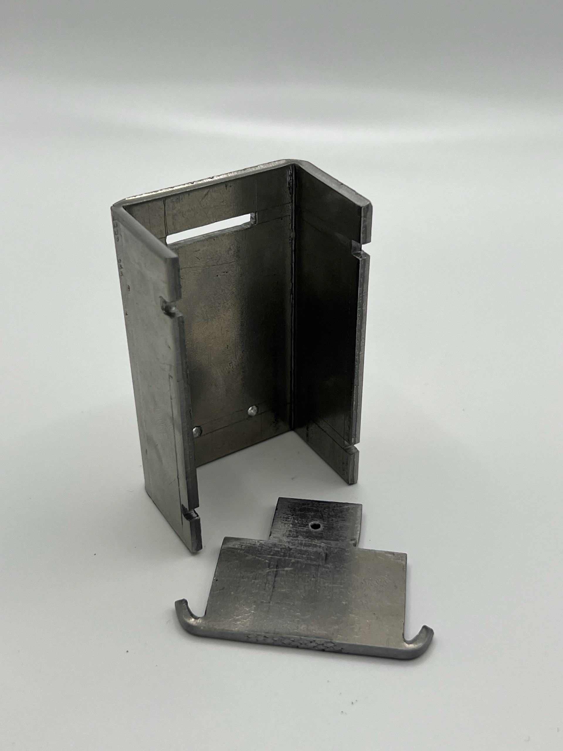
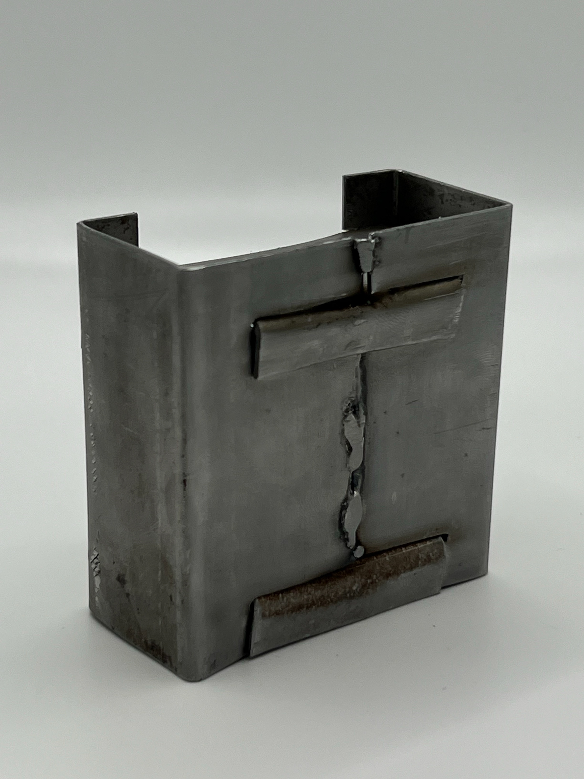
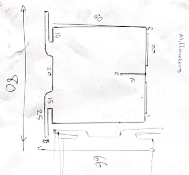
I then moved on to my final small-scale sample. This one came together really well. It had some flaws, like the front corners being too big and covering too much space, but despite aesthetics, it really helped me resolve how this idea came together.
By taking what I had learnt in my previous samples, this sample had a lot more design considerations. I made sure to reduce the thickness of the material; this is when I started using 1.2mm steel sheets. I also added extra tabs along the back seams, which I then added cut-ins onto the shelf design, allowing them to slot together.
This design did have a few faults when the parts came together. I struggled to connect the final side panel as the corners of each shelf seemed to get in the way. To resolve this, I cut a small segment of the corner of each shelf component.
Refining the design
SCALING IT UP
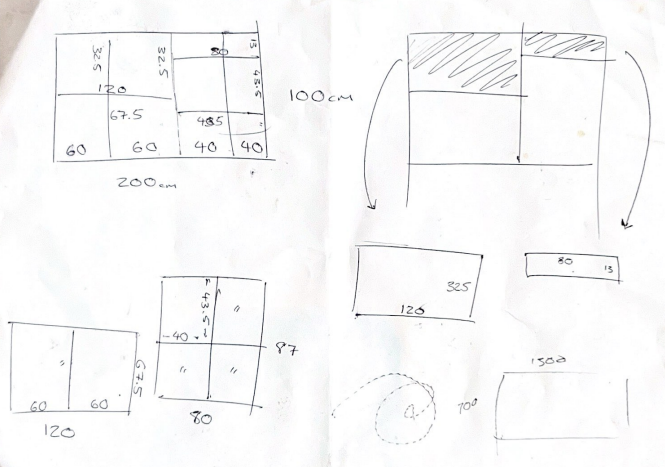
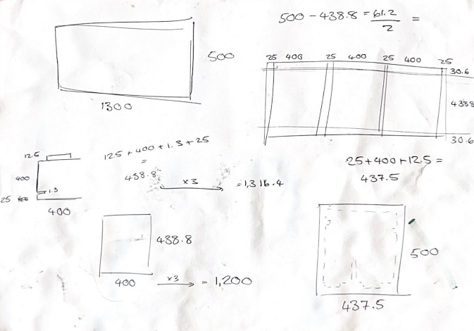
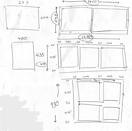
It was at this point during a tutorial with Geoff that he suggested it was time to start scaling it up. He set me a soft deadline and asked me to research and have a 1:1 scale model of this piece. Straight after this tutorial, I booked my induction for the waterjet cutter. As I could only book the induction for the following week, I knew the least I had to do all my research and come up with the final dimensions.
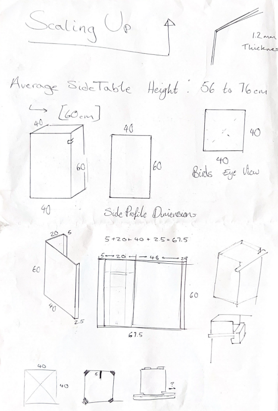
This is when I came up with the final thickness of the material and all the dimensions. I looked at the average side table dimensions and made mine a little bigger, as I want them to be statement pieces in a room, and I also wanted them to be able to hold more, so making it bigger increases its storage.
I still wanted to create a model, so I tried creating it with scrap corrugated cardboard. I had issues with this as the scrap pieces had folds, which affected the structure of the piece. I also struggled to get scrap pieces big enough for the dimensions I needed.
After someone saw me struggling to put a model together, they suggested I buy some grayboard from the Make More store as it was cheap and was good for making larger-scale models. I took him up on this and went to buy some grayboard. As I already had all my dimensions It only took a couple of hours to put this piece together. You can see my process for this below.
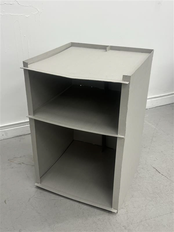
Creating this sample really gave me an idea of what the final piece was going to look like. Now I needed to get into the engineering room and bring this design into metal.
Learning the Waterjet Cutter
A big part of this project for me has been in the Hard Engineering building at the university. I had spoken with them and used this water jet cutter for a previous project but what has changed since last year is I was now allowed to get inducted and run the machine by myself.
Before using the water jet cutter, you need to have your DXF files ready. Initially, I was creating these designs in Adobe Illustrator. This was because I lacked the skills in fusions at this point. During the induction, I created a design to test the tolerances for the slot mechanism; this was with different width gaps, which was the same idea as my perspex tolerance tester.
As I had created the digital design in Illustrator, the dimensions weren't exactly accurate despite converting the page into mm instead of pixels. This means this tolerance tester wasn't accurate enough to work. Once Harry (the engineering technician) saw this, he offered to help me understand the basics of Fusion360. We sat together, and he showed me step by step how he would draw it. This was so helpful as I had tried learning it with my peers who have some more experience with the software and I had also tried to do online lessons but as I didn't know the basics of navigating the software, I found this session with Harry incredibly useful. I came away from this session confident in creating my own designs on fusion after just a 30-minute session with Harry.
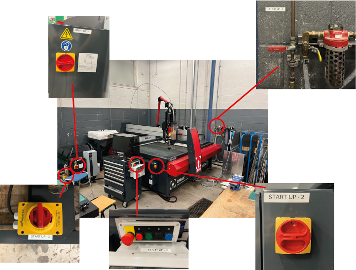
Despite my design being a bit of a failure during my induction, I still learnt a lot. The first step in understanding how to use this big machine was to learn the initial setup. There are five main switches you all need to switch on in the correct order. Below you can see the layout of the machine and where each switch is.
Once you have the machine switched on, you now have to import your DXF file onto the computer, which is linked with the waterjet cutter. To do this, you need to put your design onto a USB stick so you can easily transfer it onto the system. You then have to open the file in OMAX, which is the name of the corporation that makes the machines. This program is a CAD package, which was another software I had to learn to navigate.
On my third or fourth session in the engineering room, I was comfortable enough to use the machine by myself. There were times that I needed Harry's reassurance that the sheet was flat or that I had done everything on the OMAX software properly, like making sure the path was set to cut on the outside of the piece instead of the inside. This is a process video of me cutting the shelf to my final piece. The reason I annotated the video with how much I sped up each clip is so you can understand how time-consuming it is to set up and cut this machine.
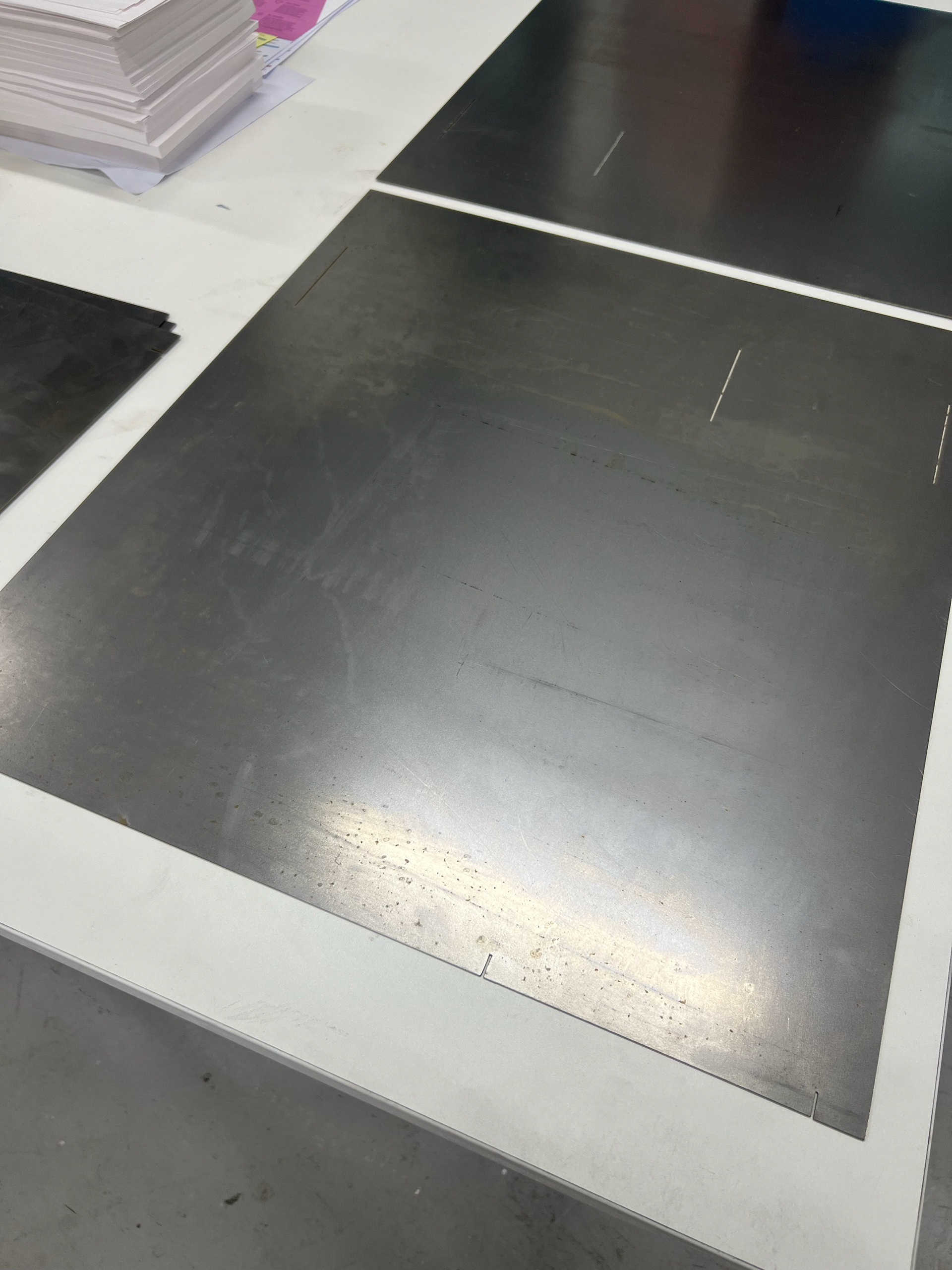
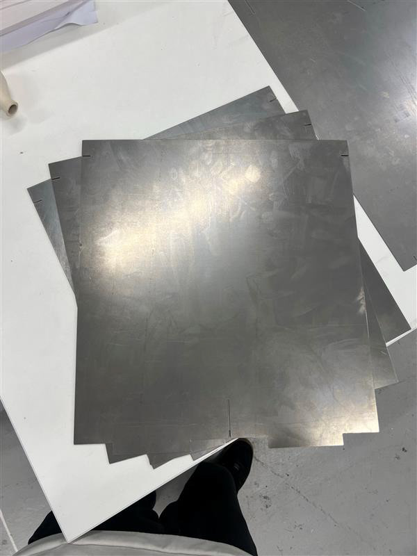
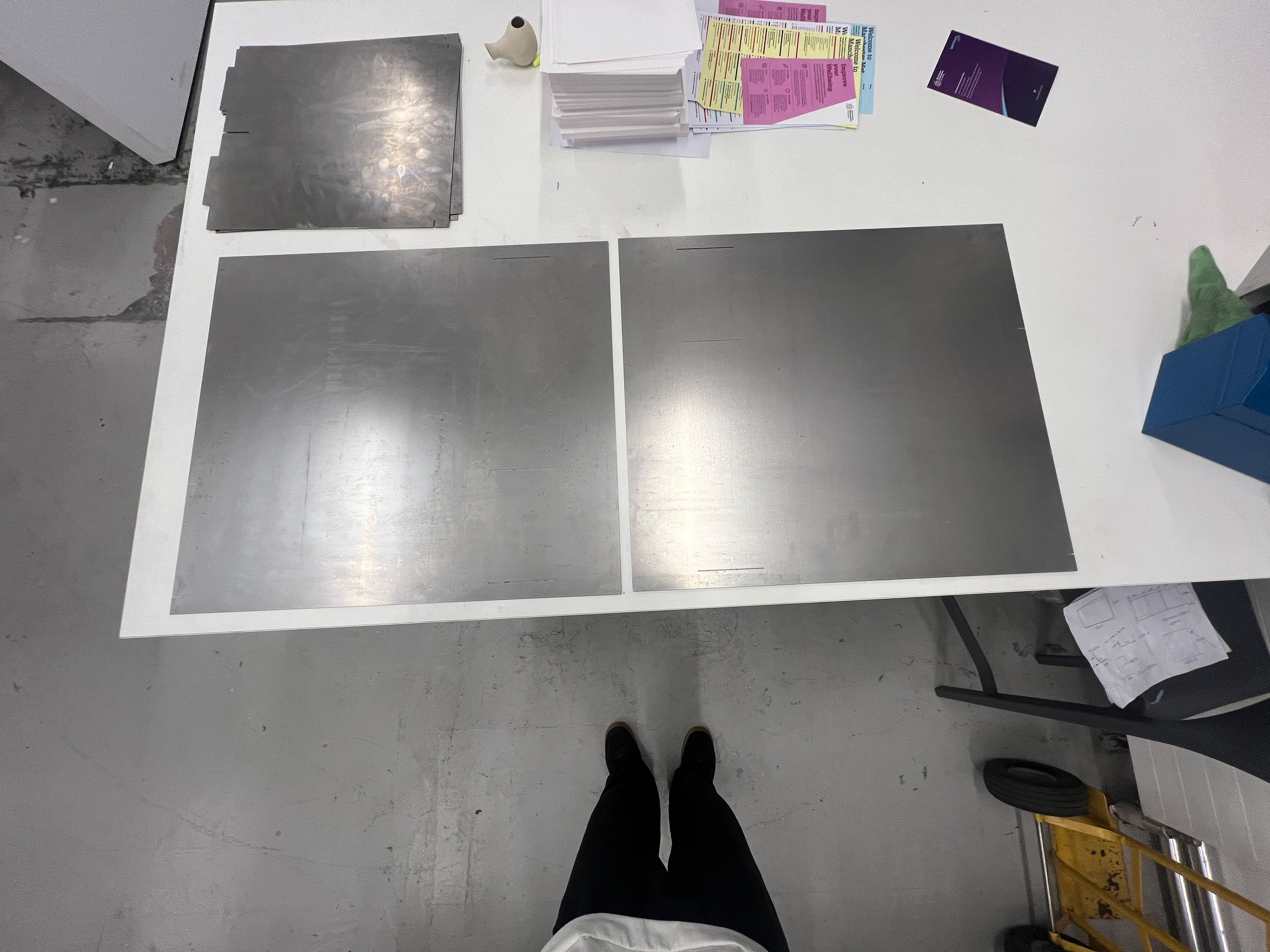
These are the cut sheets I'm left with after my sessions using the waterjet cutter.
FUSIONS 360 DEVELOPMENT
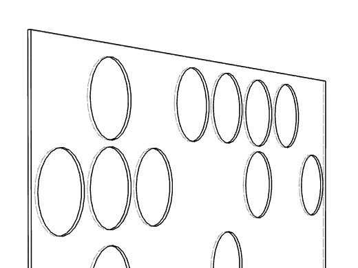
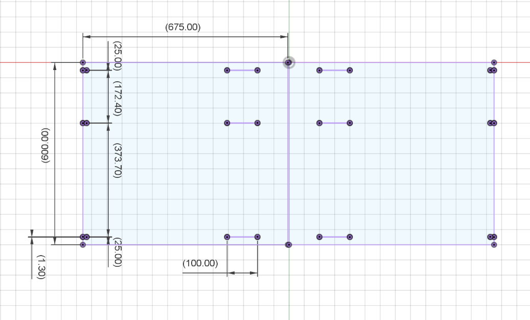
These are the templates for my final design, which I modelled on Fusion after my lesson with Harry. I'm aware there is still so much to learn, but I'm hoping to do the AutoCAD exams throughout next year before graduation to get the AutoDesk certification.
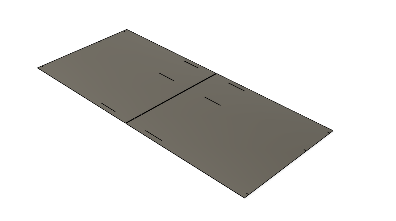
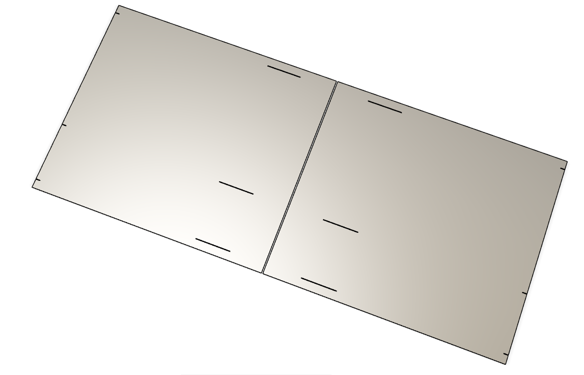
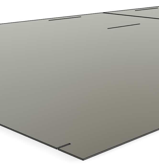
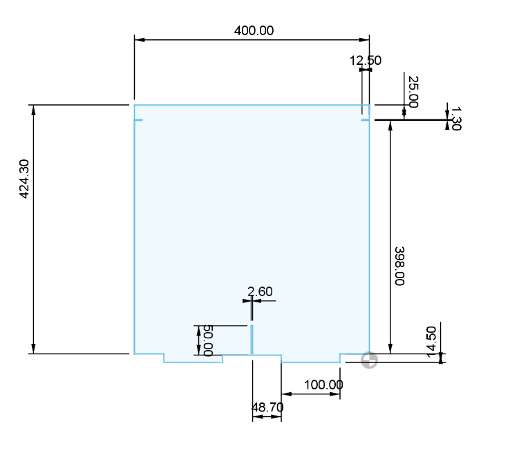
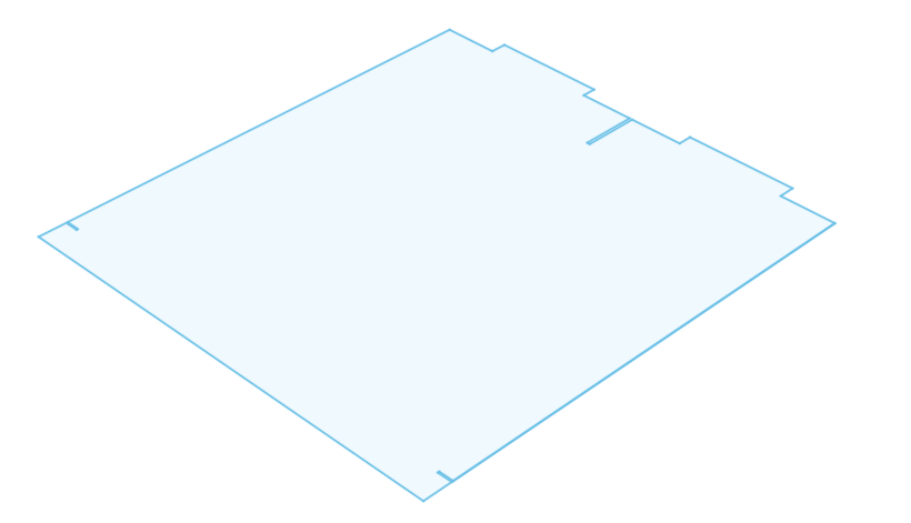
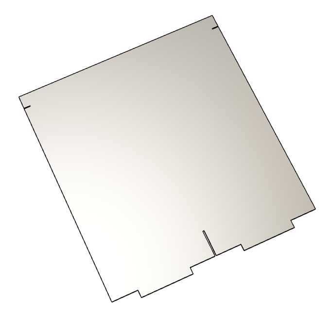
These are the templates for my final piece; however, I've also been doing fusion work for other projects I'm working on, which I'll show below. I know I still have a lot to learn as most of these models have been from 2D planes. I wish to develop my CAD skills further and get the certification before graduation, as it's an avenue of design I've become very fond of.
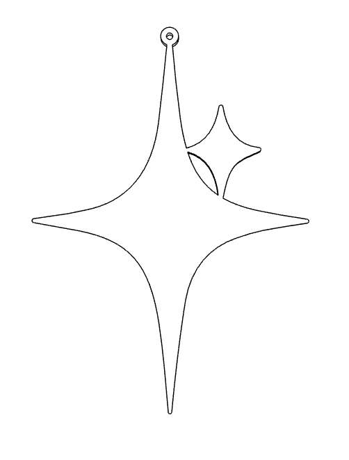
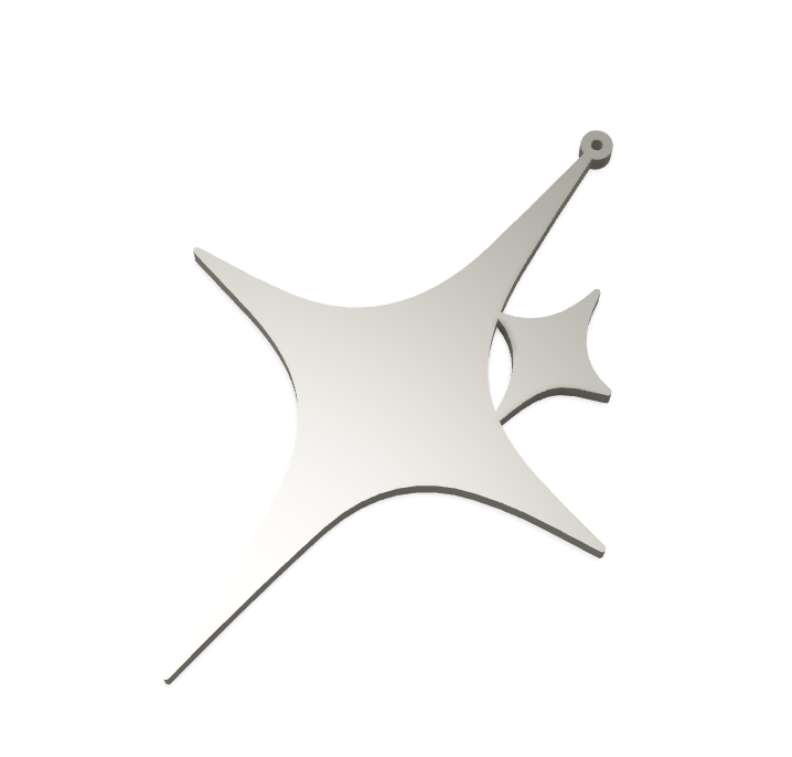
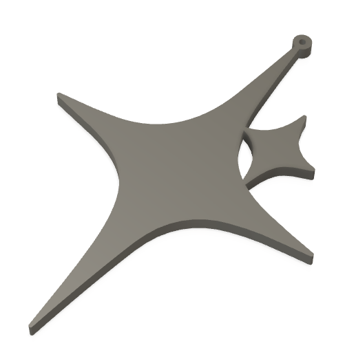
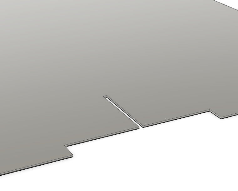
These are for a commissioned project for keychains, which will be sold at UniTom in the new year. I thought I'd show this as I'm trying to externalise my practice with my newly improved fusion skills.
BUYING THE MATERIAL
I only used 3 materials throughout this project, including acrylic, grayboard, and steel. For all the material sampling I used, I spent no more than £20. I brought 2 sheets of perspex (acrylic) and 3 sheets of grayboard; I can't remember the exact price of these sheets as I had forgotten to document it at the time.
When it came to sampling with steel, I mainly used small offcuts for the samples. For the final small metal, I brought a small sheet of 1.2mm thick mild steel, which cost £3.28.
For my final, big sheets of metal cost more, so I tried to understand my design properly so I did not waste any money and sample on a larger scale; this is primarily why I first scaled up my design with Grayboard. The first sheets I brought cost me £32.48 When measuring these sheets and cutting them to the side, I left 10mm around each edge. I thought this would be enough room to clamp the material down, and I did this to save money. This ended up not working. On my second session in the engineering room after we had set everything up and got my design onto OMAX, we were trying to set a home point for the arm of the machine. These are just base coordinates for the machine to start from and return to before and after cutting. When we dry-run the design across the sheets I had brought, we were struggling to line it all up as there wasn't enough room around the edge of these sheets for me to clamp to the machine. Before we tried cutting, I suggested to Harry, who was still helping me at this point, that we leave it and I book back in later that week if he was free, as if I had cut the metal, I wouldn't be able to return it to the metal department. As I still had big untouched sheets, they let me return them and cut some bigger ones, leaving at least 25mm around each edge. I did this and paid the excess, as I had already paid most of the bill.
I didnt need to pay for the garnet in the waterjet cutter as it was covered by the course however it is another expense i would have to consider if i were to make these outside of university.
The price of the final sheets worked out to be £38.52.
As I created 2 of these, the price of the material cost £77.04.
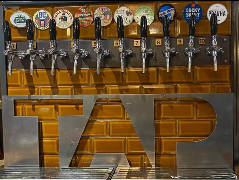
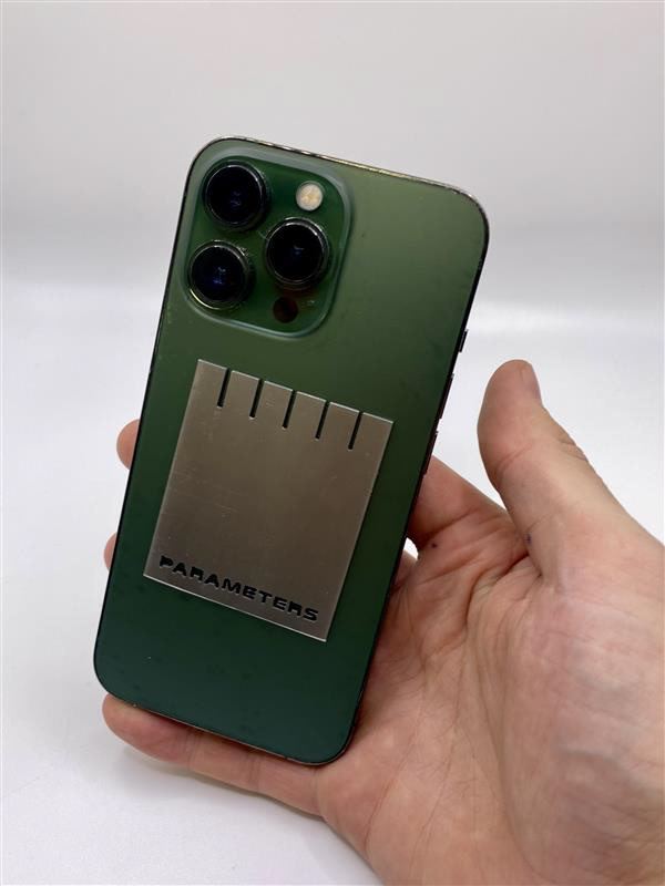
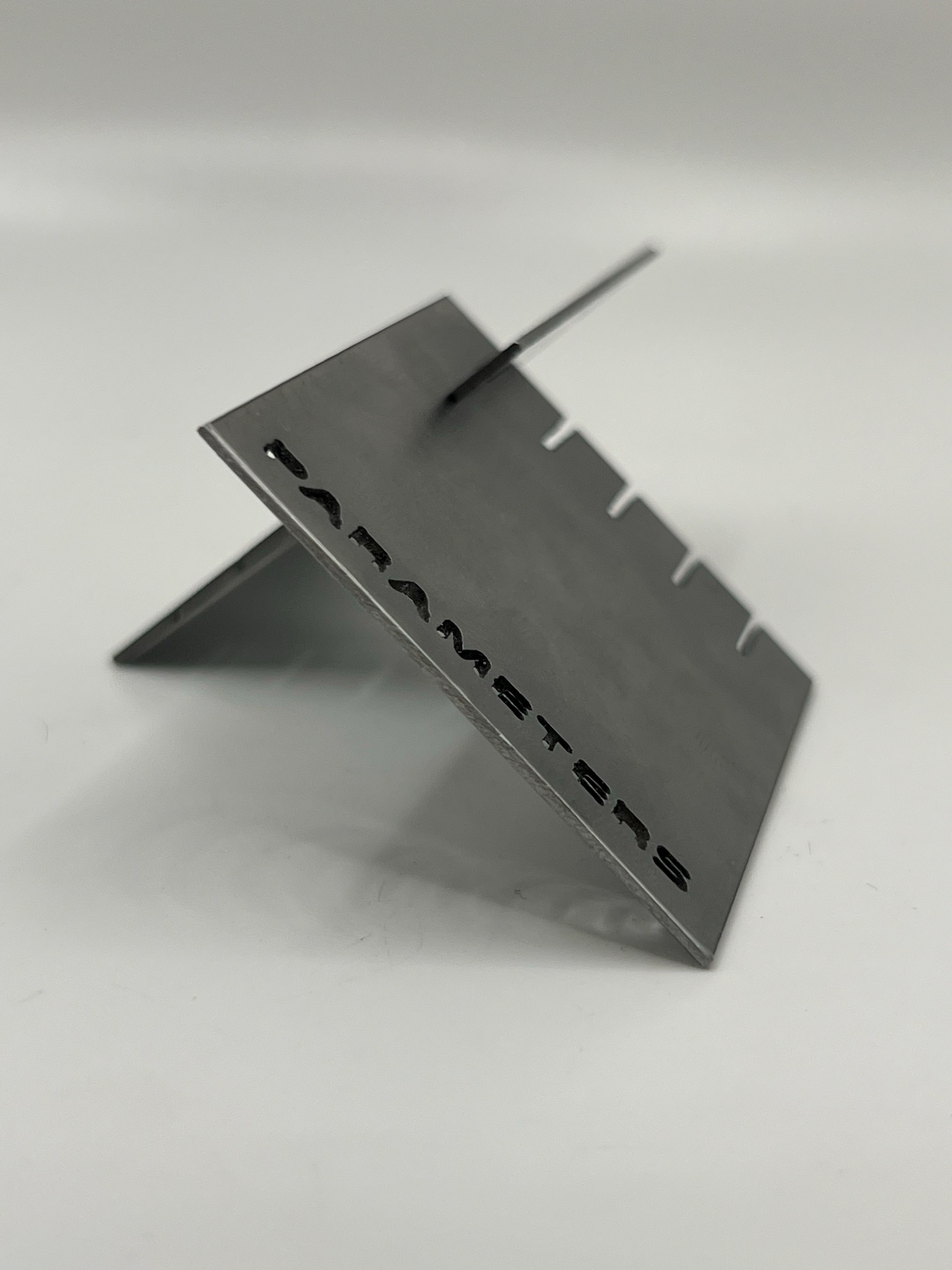
As I also brought a sheet of metal for the TAP sign for the event organiser that cost an extra £20.40.
The overall cost of metal for the final pieces and this sign was £97.44
External Pricing
If I were to create this externally outside of the university, I would have many more expenses. I would have to pay for materials, which I suggested I would like to make with stainless steel instead of mild steel. I would also have to pay to use or order my materials to be manufactured to the specific standards I need to be. This would include waterjet or laser cutting, bending, and finishing.
I found a place in Sheffield which do services for waterjet cutting. I've added the link here. I've requested a quote for my pieces but have not heard back just yet.
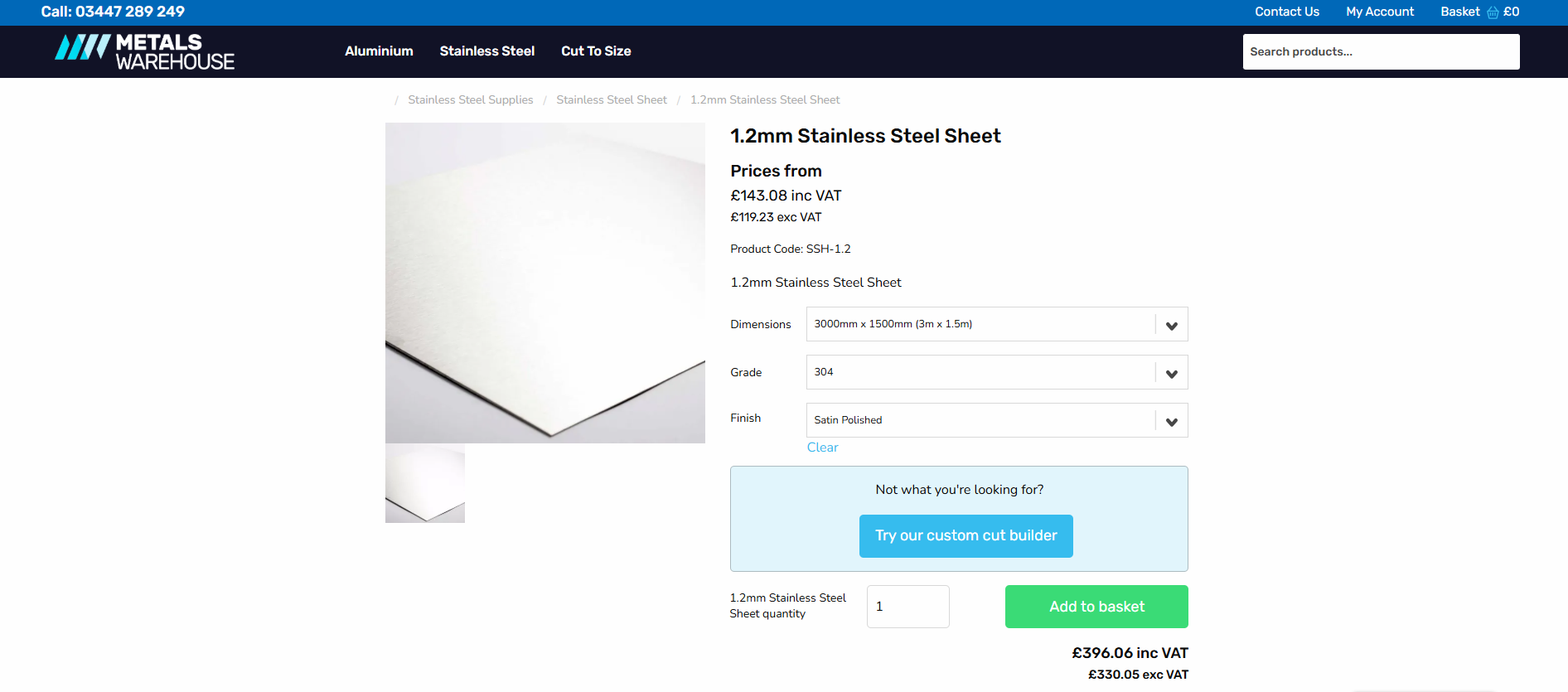
The price for 1.5 cabinets in material costs for stainless steel would be £396.06 I don't believe this includes delivery. This means that 3 cabinets would cost £792.12; this is before all manufacturing, shipping, and packaging costs.
SANDING
A crucial but boring part of my whole process was giving it that brushed finish. I won't go into huge detail, but I spent a couple of hours brushing/rubbing the flat sheets with an abrasive rubber to achieve this look. This is actually one of my favourite tools, despite it being one of my least favourite parts of this process. This tool is like magic and removes the surface layers of oil rust and material, leaving you with an amazing brushed finish. I needed to be careful with the direction I was brushing in, as you can see the streaks depending on which way you brush; similar to painting. Here is a short video of this process.
FOLDING
Folding the sheets was a big part of my process. This was a make-or-break moment, so I was initially scared to fold any of the components, as I knew how long it took to waterjet cut the pieces. This stage also required a lot of precision, as I later found out that the bend could be 1 mm out and cause problems.
I first marked out where I was bending these by carefully measuring the distance between each fold. I had already worked this out when I scaled my design up, but now I just needed to make it as accurate as possible. The back and side panels were split into four sections, requiring three separate folds. Here are some videos of this process.
THE ASSEMBLY
Now I had the back and side panels Bent into their final form, I could start assembling the pieces together. I knew it would be a struggle to get these pieces together, and at this point, I wasn't totally sure it would work and it would go together. Here is a video of the first time I tried to connect all the pieces. I put a white cloth up over a workbench as I wanted a clean video of the assembly. I didn't manage to get the last panel on in this video as I had to move it onto the workbench it was a bit of a hazard on the floor with all the sharp edges pointing up on a slippy cloth.
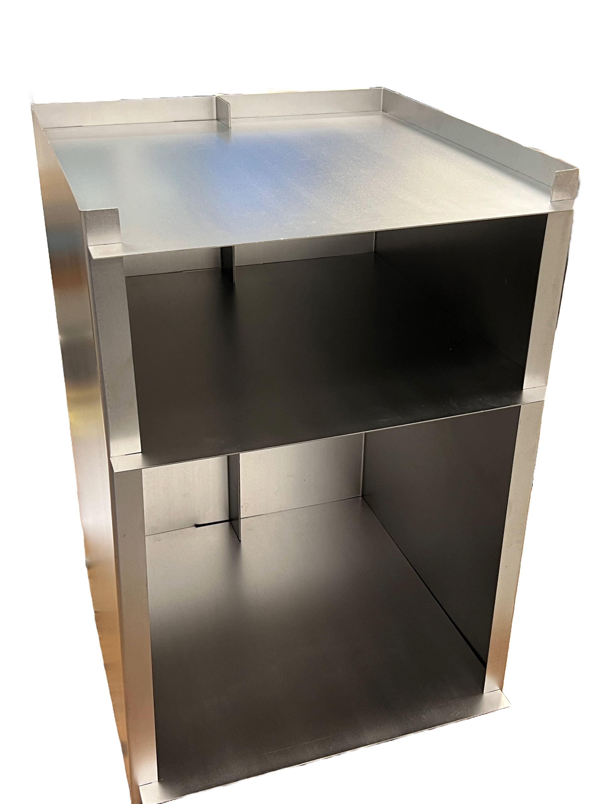
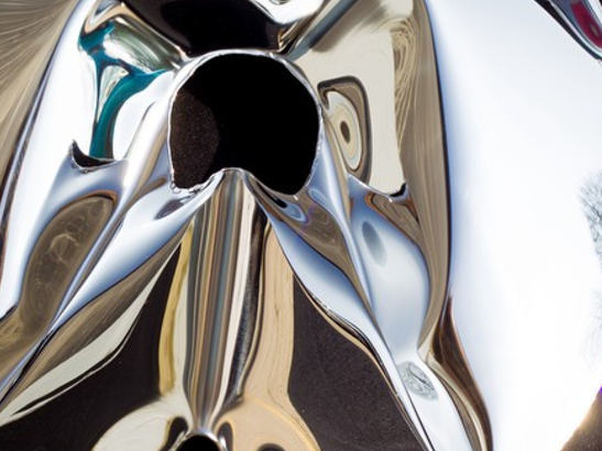
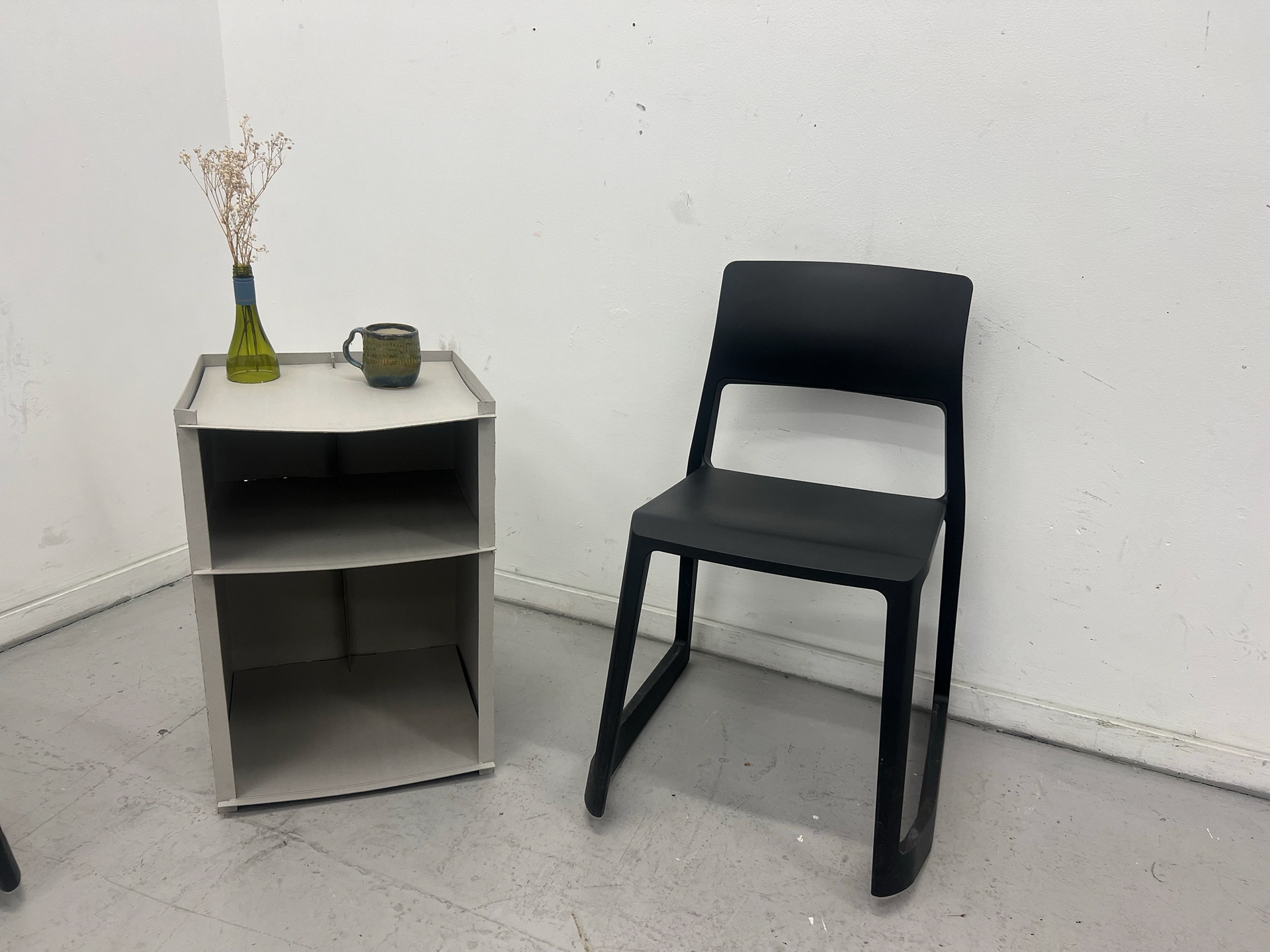
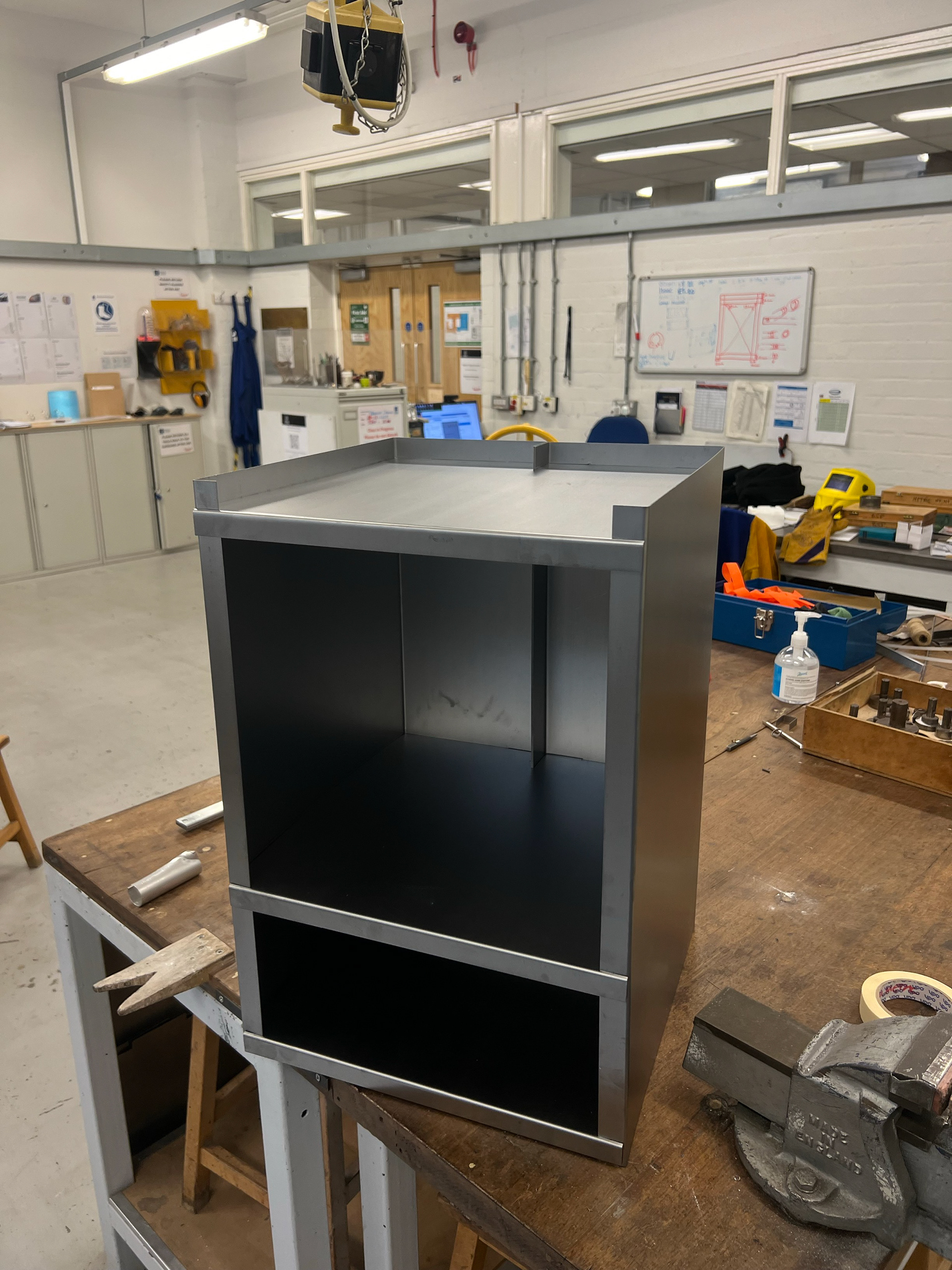
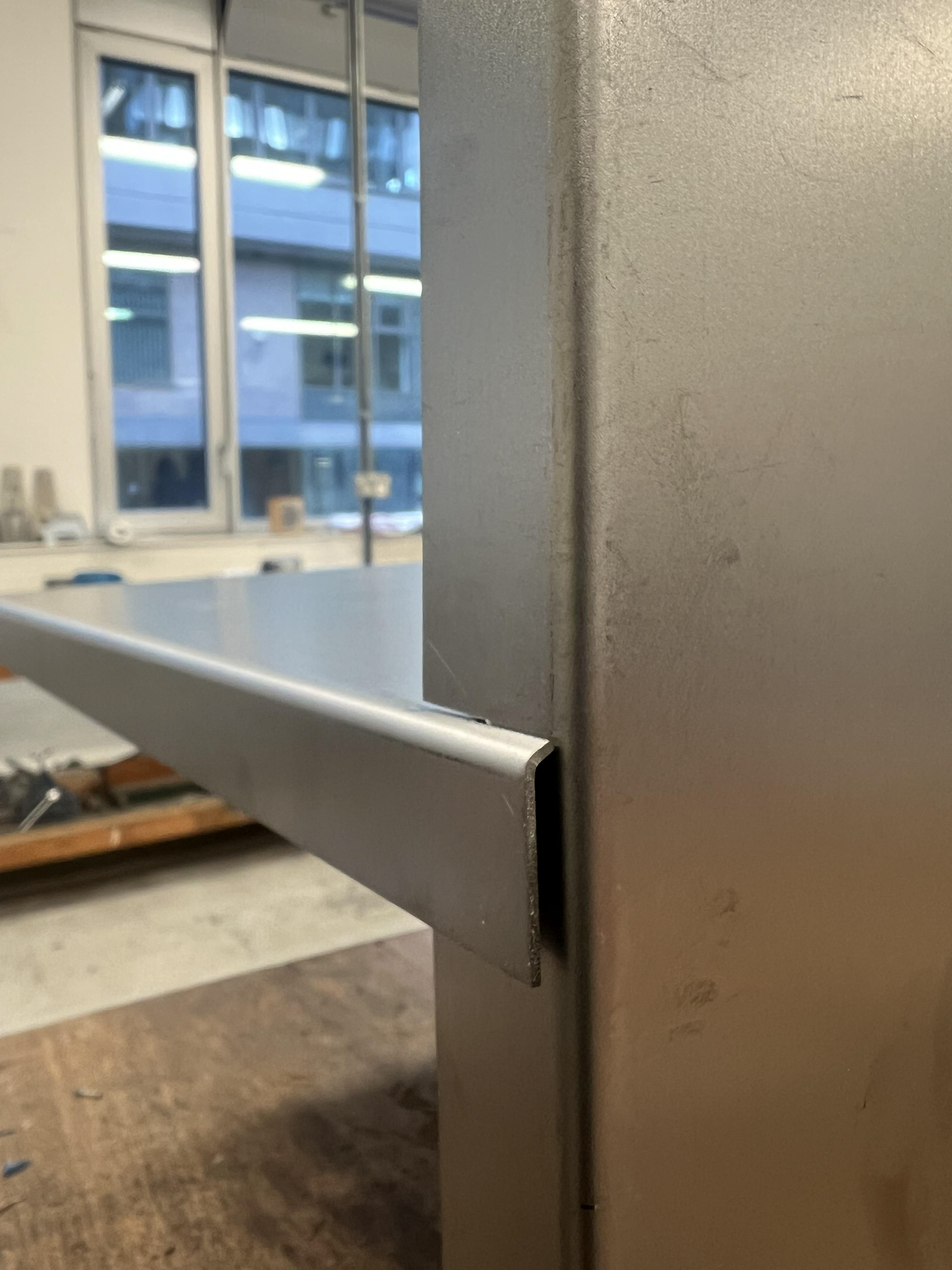
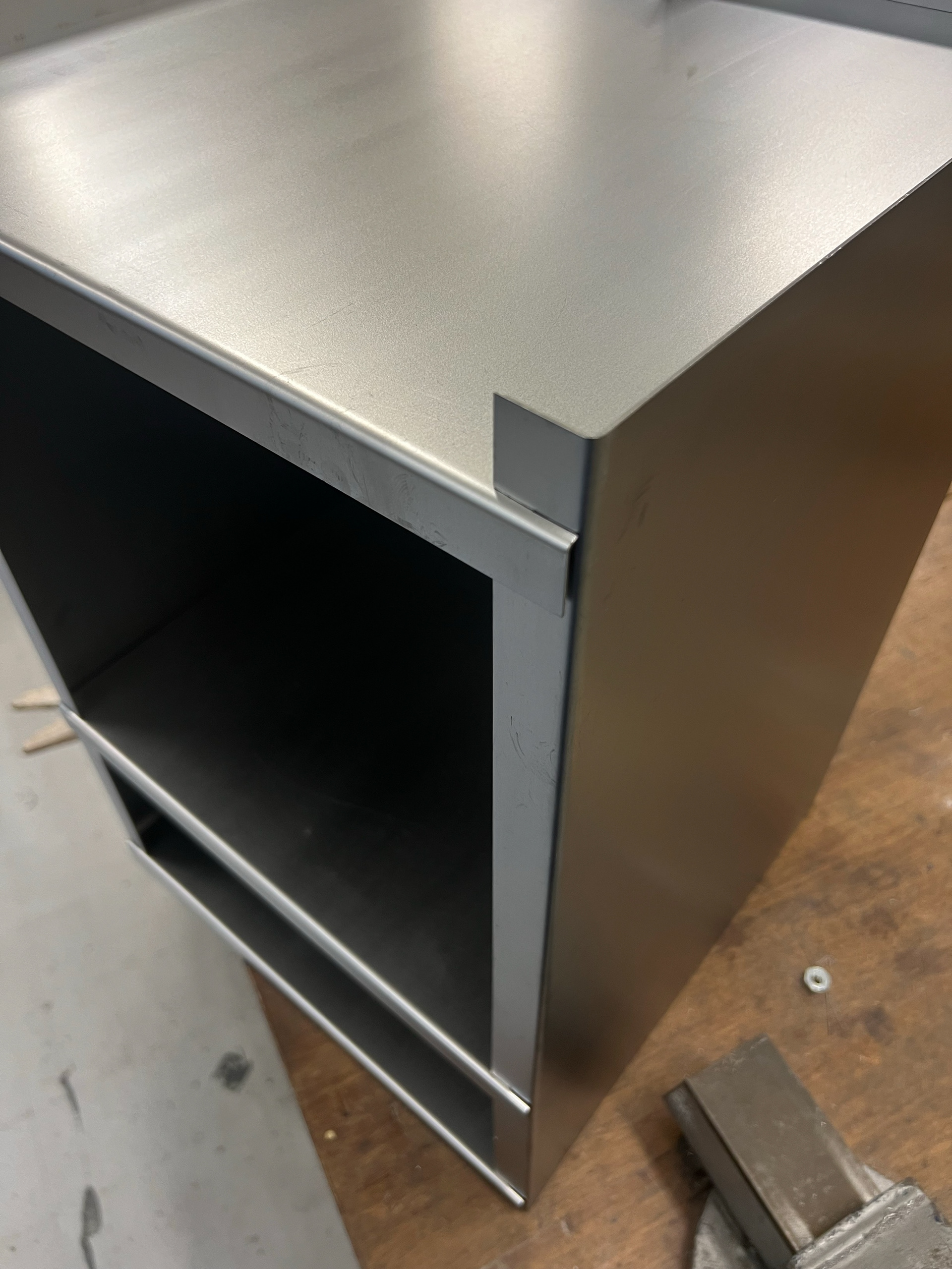
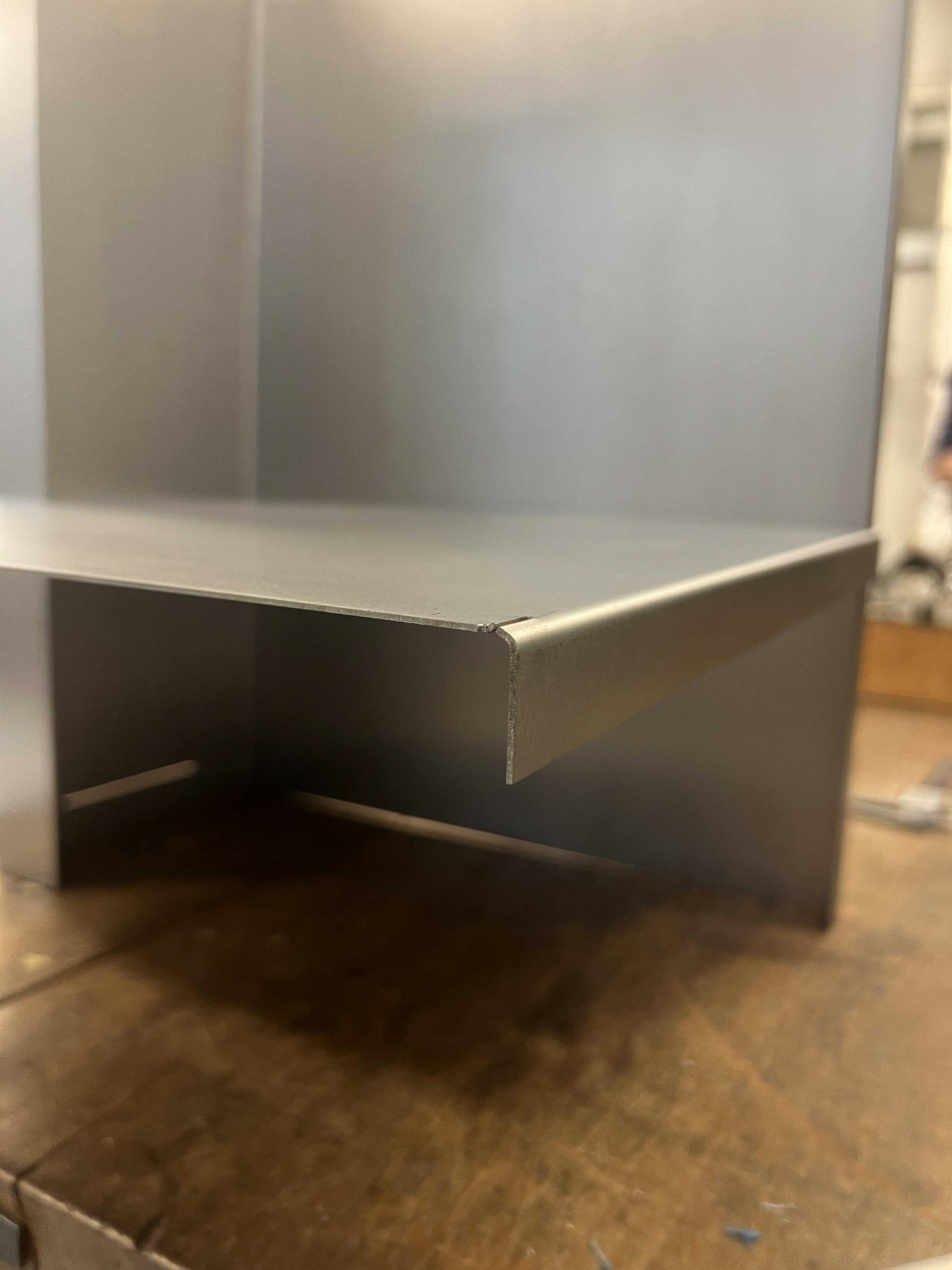
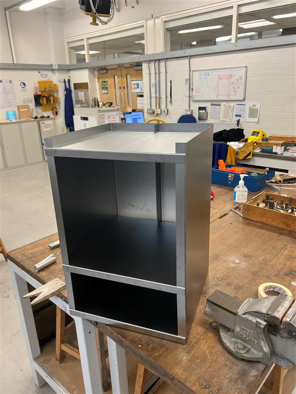
After a bit more wrestling in a safer environment, I finally got all the pieces to click together. I was astounded by how well they all came together. There were a few initial concerns with the metal flexing in certain ways, but I was very happy with how it came out. I've put more images below so you can see how the first form came together before folding all the tabs and locking it together.
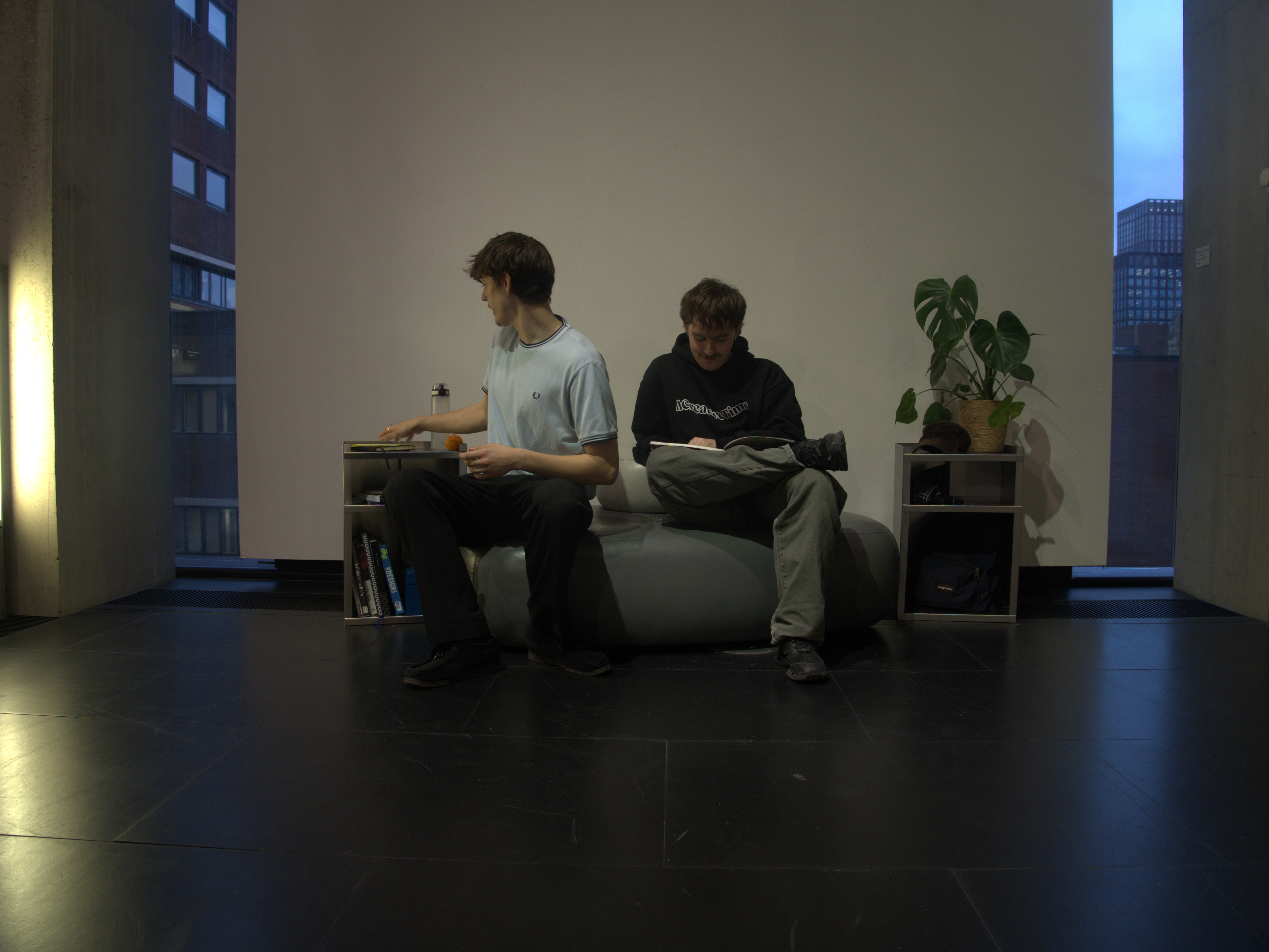
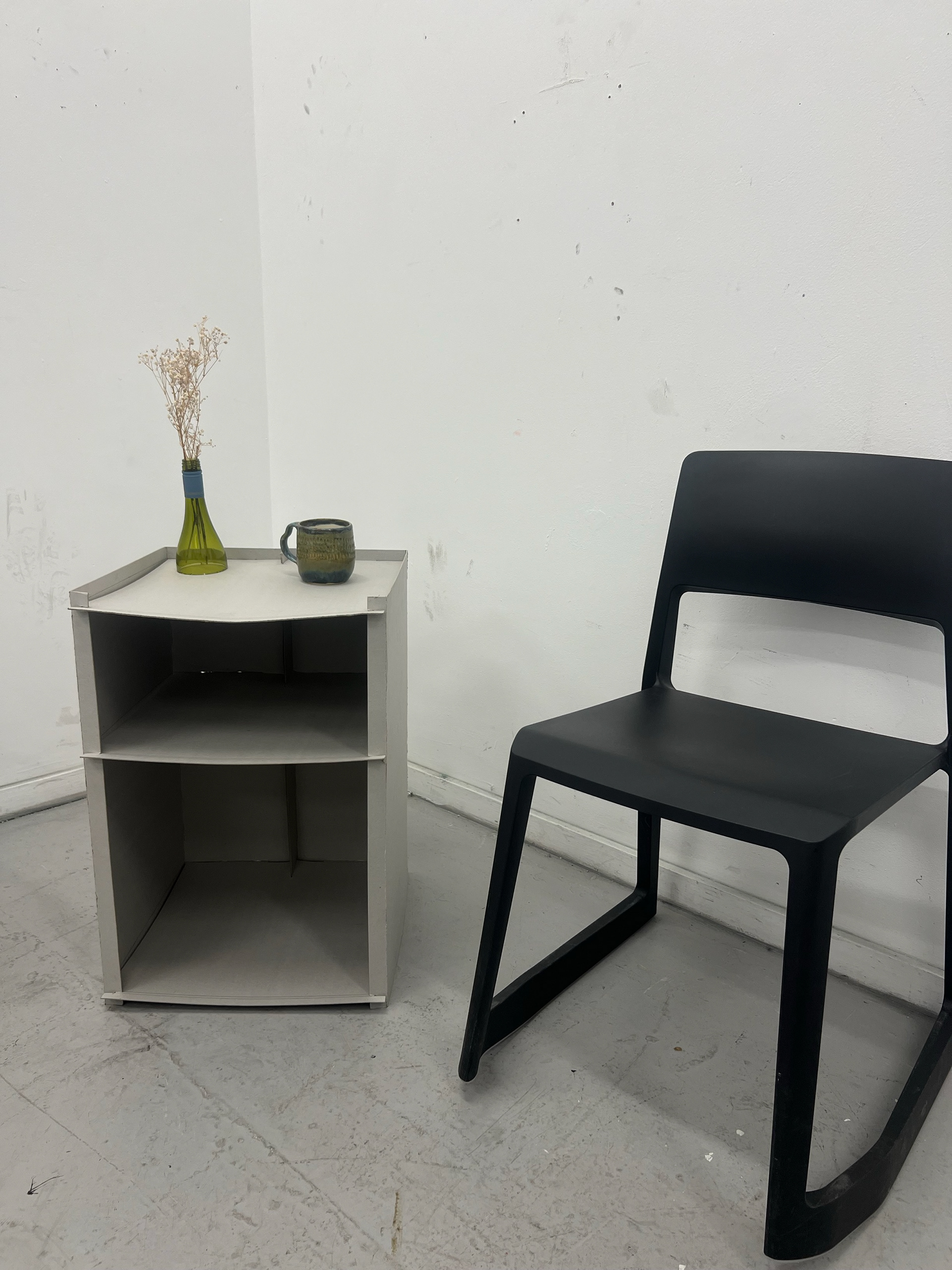
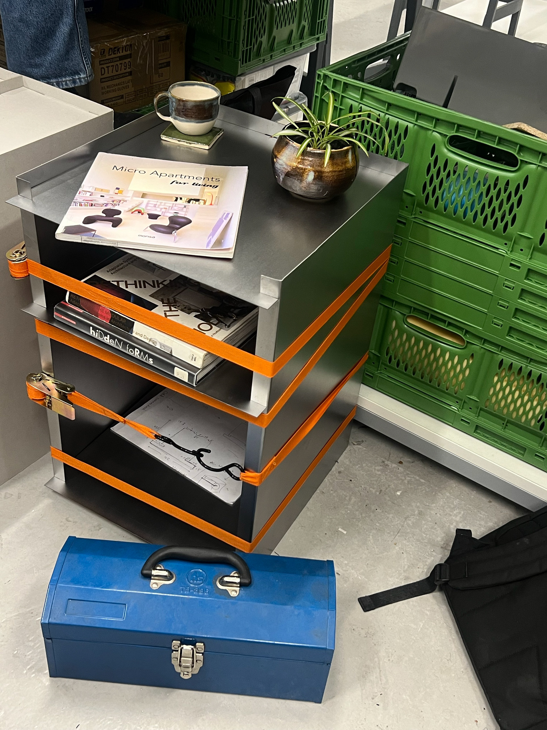
As the material was still flexing, I thought if I strapped ratchet straps tightly around the shape, it would hold its shape together. I really think this worked well, as it's much stronger than the second one I made, where I skipped this process. I also like the orange and steel aesthetic, so I got my first 'context' picture with my unfinished piece. I've added them below.
THE TABS
Once I now had my form put together, there were some final steps to complete this piece. I knew I wanted to fold the front and back tabs, but after the form came together, I was scared to ruin what I had so far. I initially thought I would have to fold the tabs with a block of wood and a mallet, but then someone suggested I fold the fronts of the shelves before assembling. This worked because, at this point, the shelves weren't locked together yet. This meant my work was actually modular, as it would still break down into its original components.
My first step was to get back on the bending machine and bend 22mm in from the frontfacing edge. I marked this out with a rule and scribe
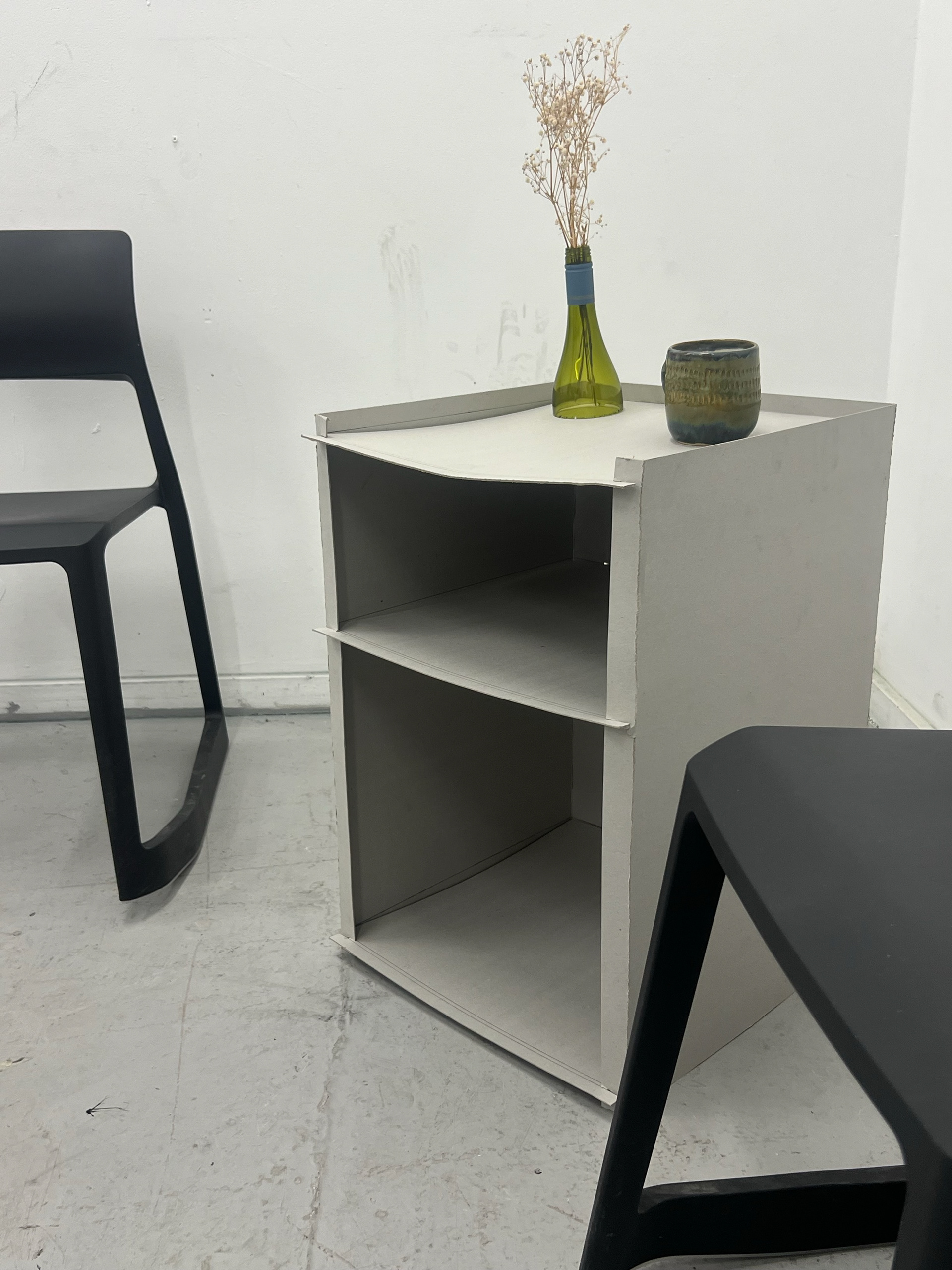
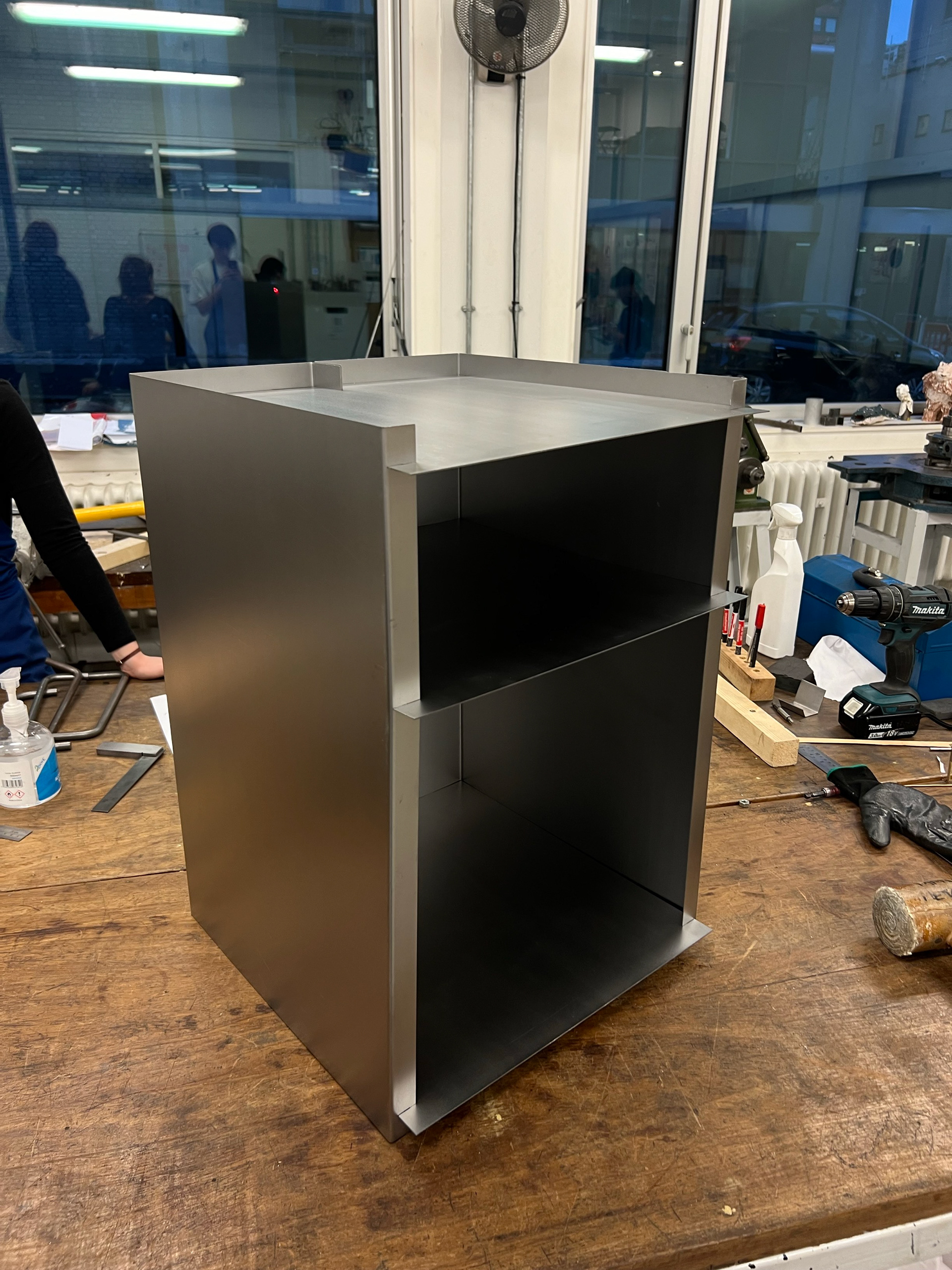
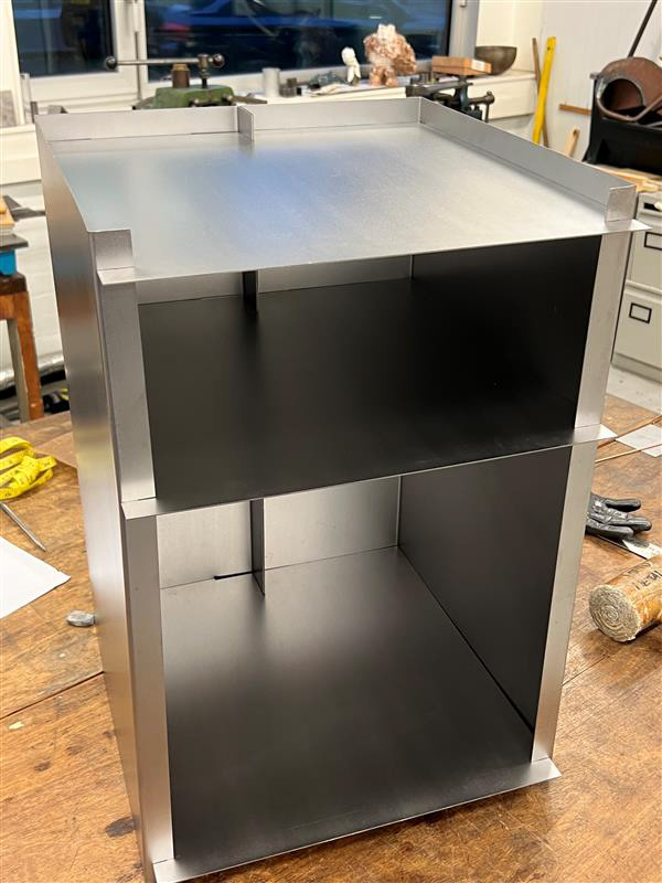
These videos show my second assembly process, putting the final bent shelf components together. The images below show me putting them together in their not-intended form. This meant that the big shelf was above the smaller opening. I quite liked this, and it played into the original idea of modular furniture, which I was trying to convey. This also helped alot with the structural integrity of the piece, meaning I didnt have to fold the tabs at the back...
I ended up leaving the back tabs unfolded to allow users to assemble and disassemble when necessary. This was a full-circle moment, as I thought I wouldn't be able to create anything modular. I was happy that it didn't need to be multifunctional and served its intended purpose perfectly.
FUTURE CONSIDERATIONS
STABILITY
If I were to take this design further into manufacturing, there are a few things I need to further develop. Firstly, I need to make this design 100% secure and stable enough to withstand higher amounts of pressure. For this, I would possibly use a thicker sheet of steel. Despite the fact the 1.2 mm thickness of the material has been a key feature of this project, it still doesn't have the highest level of quality of function due to this. There are alterations I could make to the design, like adding slots and tabs along the sides or adding tracks for the shelves to lay on, preventing it from bowing.
BASE
Another addition I wish I had time to make would be a more suitable base for carpets and more delicate flooring. As there is tremendous pressure on the thin sheet at the bottom of the cabinet, it would scratch and rip any flooring, which is something I wish I had resolved for the hand-in. The way I have thought about doing this would be with a thick strip of leather, which would be strapped around the bottom, which relieves the pressure and cushions the flooring from the metal.
Another way that Geoff suggested was to design and 3D print small feet that would clip onto the bottom and wouldn't be visible from the outside as it would direct and spread the weight on the inside of the base, which is only visible from underneath.
SANDING
Another issue I faced was the sanding to get the brushed outcome. I think as I did this by hand I was almost rushing it as it's a bit of a tedious process and you can see streaks on where I have not gone straight. I think this is a process that can only be perfectly executed when machined.
MATERIALITY
I have also thought a lot about working with stainless steel, as it is a higher-quality material for a luxury product. My issue with doing this at this stage would be the expense of this material.
FINAL FINISH
I should have oiled-coated my final piece to prevent it from rusting, but due to the workload, it was a stage of the process I could afford to miss as I knew it wouldn't have rusted by the time we needed to hand it in. I hope that it still has no signs of surface rust when it comes to marking; however, I am aware it's something that I should have done.