

My first initial step along my journey in my design and craft process for this unit was creating different forms by using plastic straws. To do this I chopped even lengths on either side of each bend, this allowed me to keep the corners consistent. I knew from our previous project that it was a chair that I wanted to make so I knew this idea would help me visualise and see different forms right in front of me. Keeping the straws a consistent colour was the right idea because it didn't distract me from the forms I was creating.
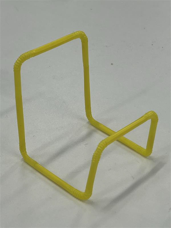
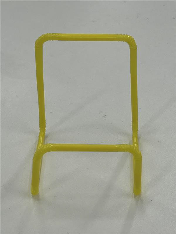
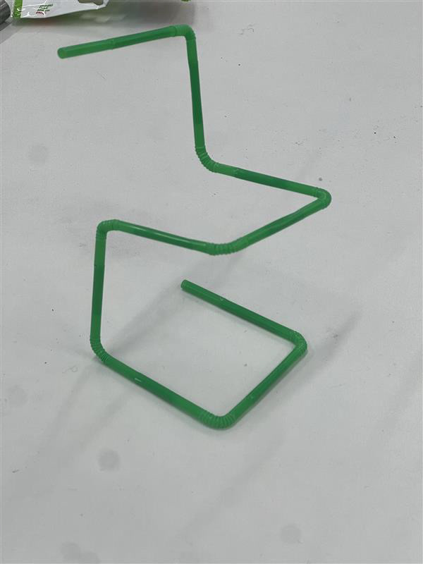
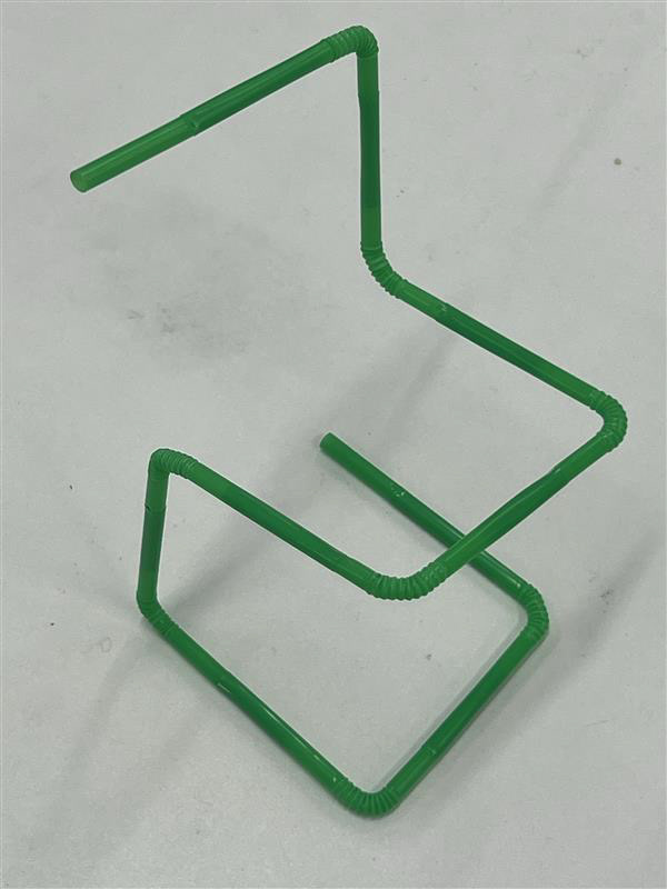
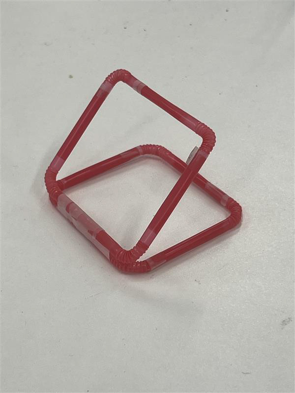
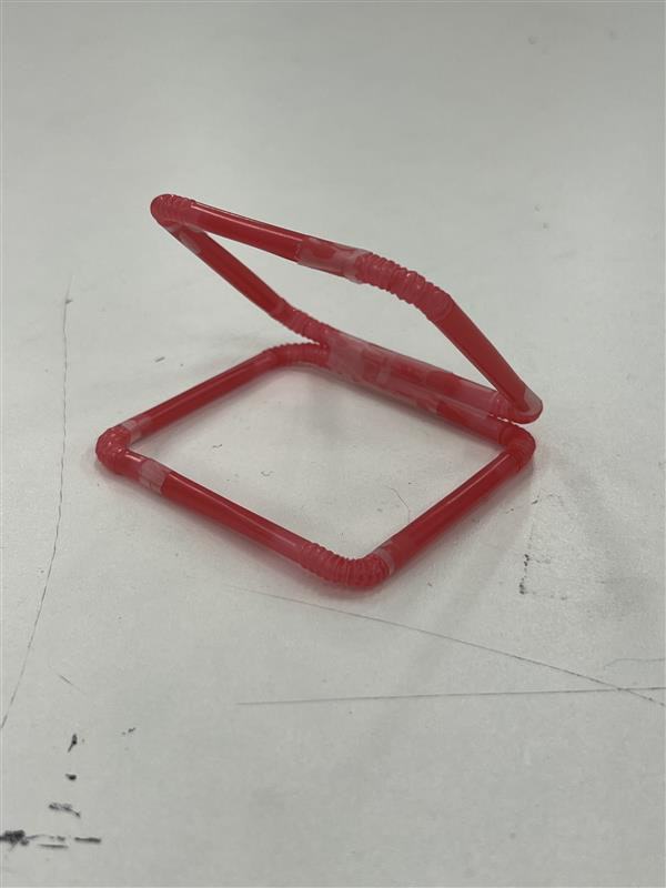
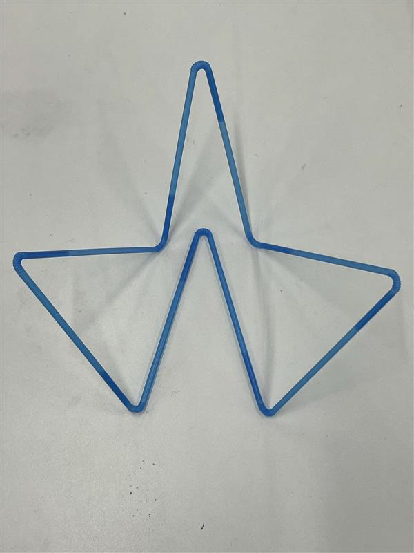
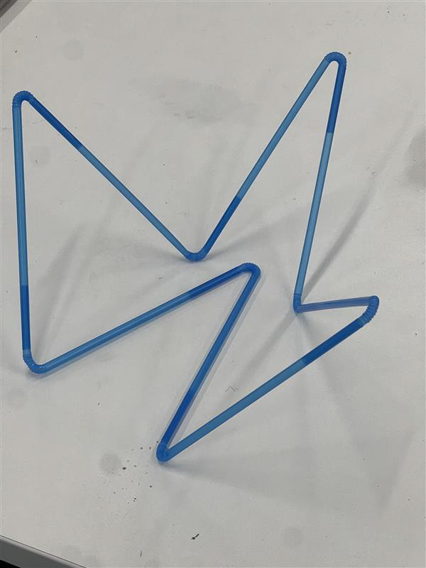
These samples really brought my ideas to life. However, I was very interested in looking at how each form is practically made from the same standardised components.
At this stage, I was also concerned with how ambitious I was being which I did not want to repeat after my last project did not turn out the way I'd hoped. I considered changing my overall idea from seating to lighting after conversations with Rachel however I understood all my previous research from uc1 was about chairs and seating arrangments. I wasn't ready to step away from this idea so I knew the best thing to do was speak with the technicians and create a full-scale sample in the workshop.
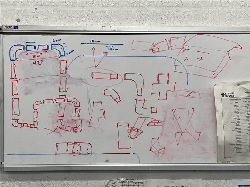
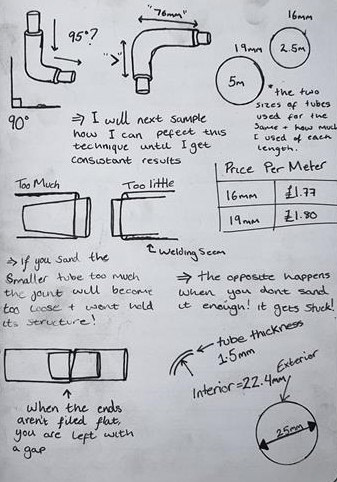
I sketched my idea on a whiteboard for the technicians so they could understand my vision. This sketch on the left wasn't at this point but was drawn later on down the line to resolve some difficulties.
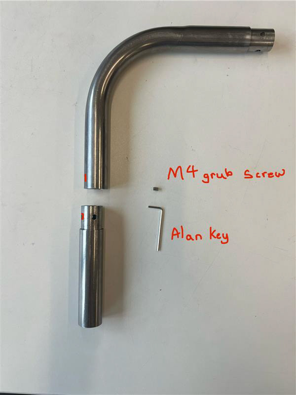
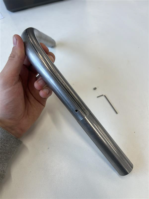
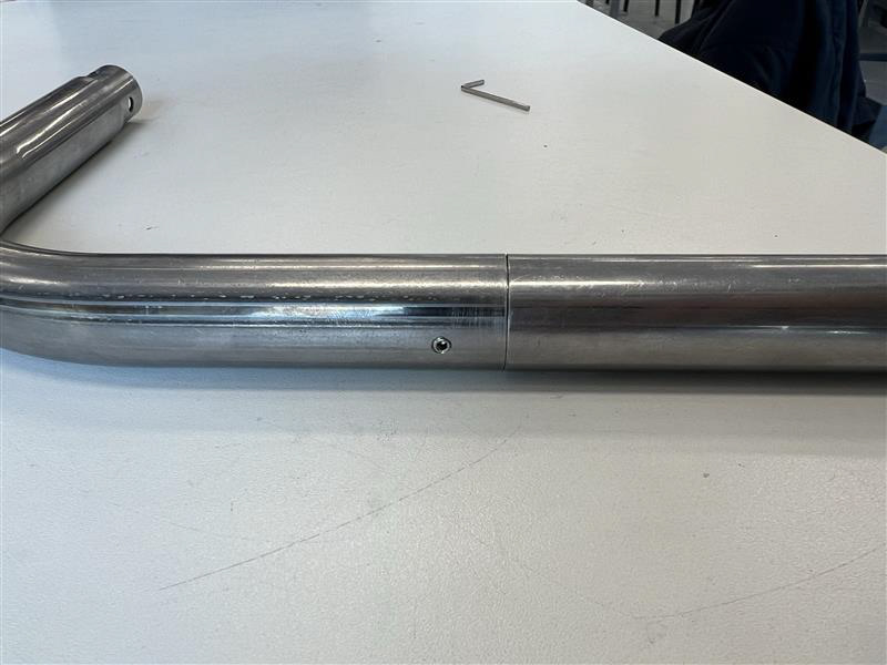
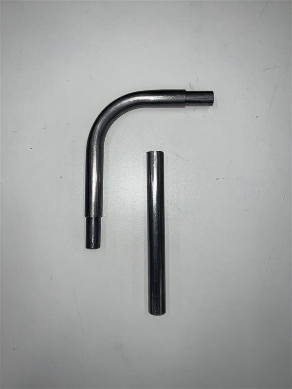
Once Paul understood my vision he suggested that I look back at the processes I sampled before Christmas for my uc1 hand-in. This was the process of getting 2 tubes with a 3mm diameter difference. This technique allows you to connect 2 tubes end-to-end seamlessly.
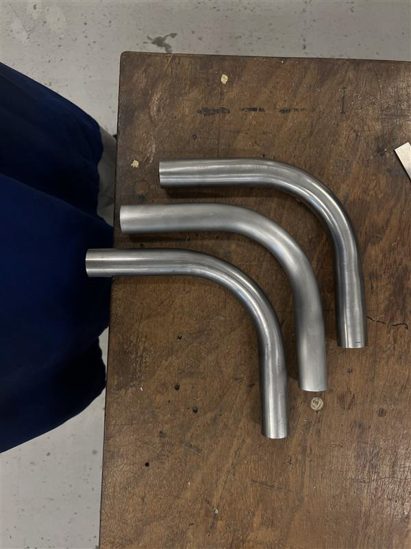
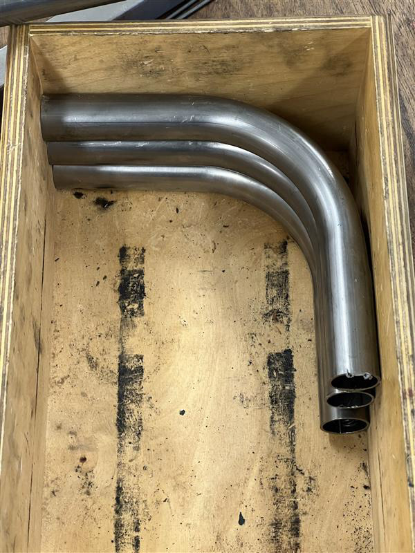
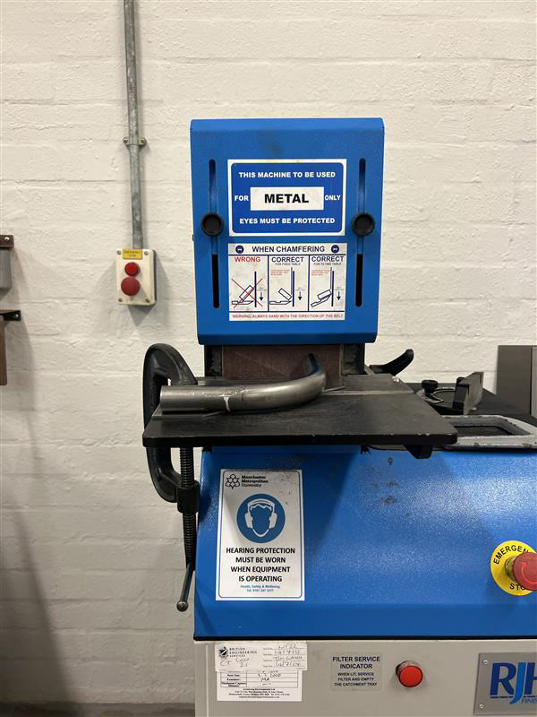
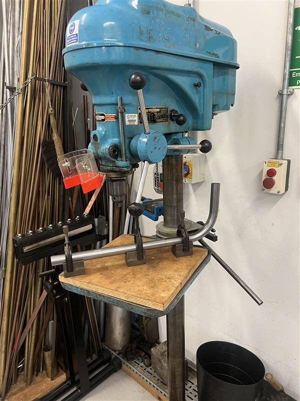
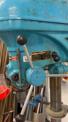
I practised this a few times and liked the outcome I got but I was unsure about the corner pieces. I was then shown and inducted on the tube bender, which gives bends to circular tubing at any desired angle.
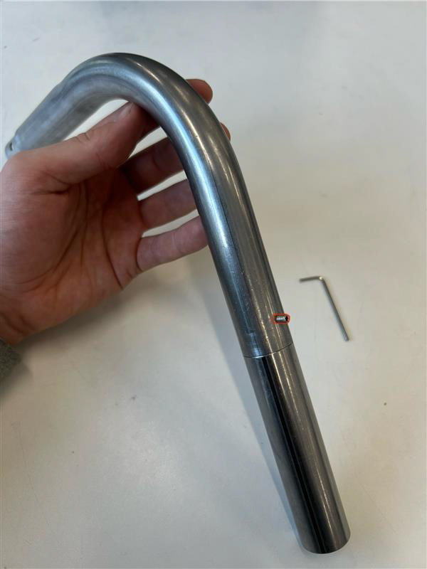
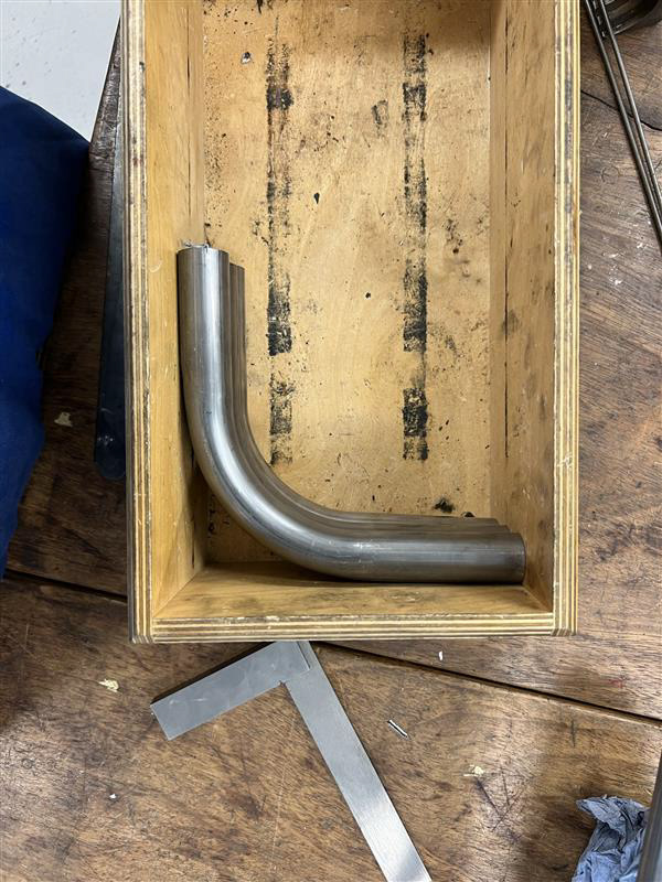
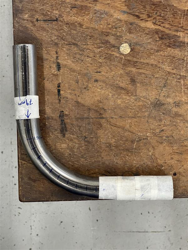
Once I had put these two processes together I had my first cornerpiece component! This was a very simple process for the perfect outcome and I was very excited as I started to see my straw designs become metal.
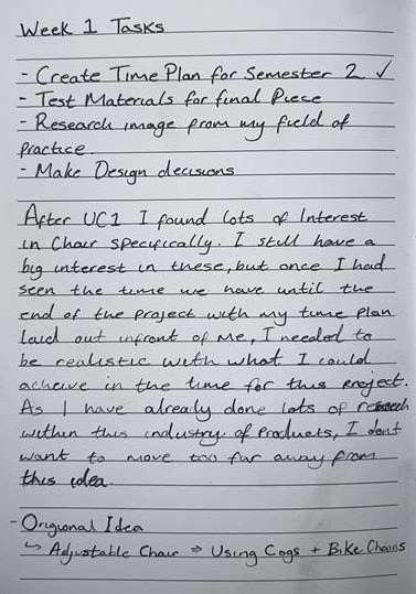
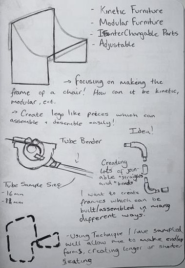
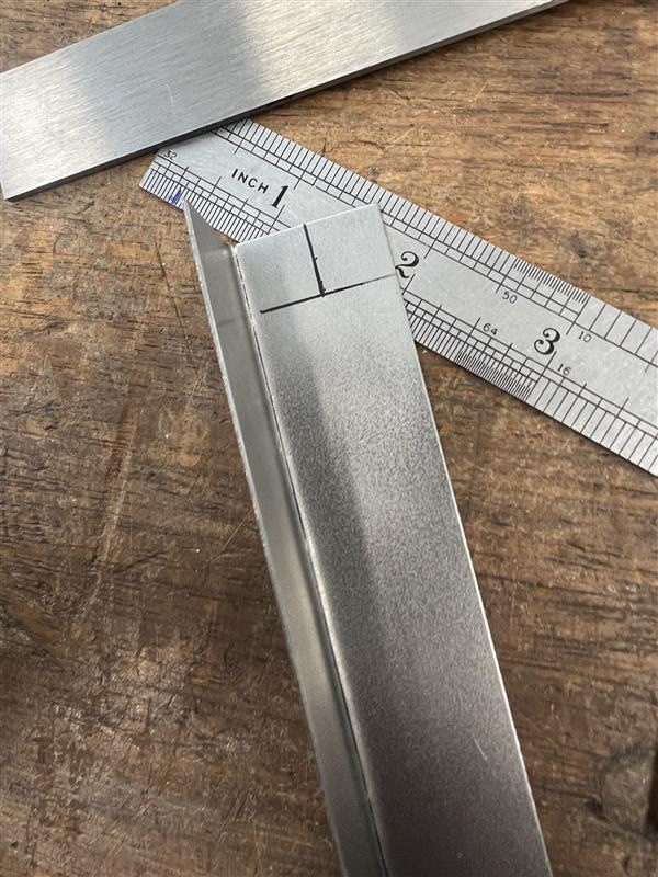
This is my sketchbook from the first week. Once I was confident to stick with this idea and I had it mapped out on my time plan, I carried on to make my first sample. I had decided to make this with 16 components (8 corners and 8 straights).
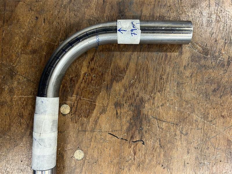
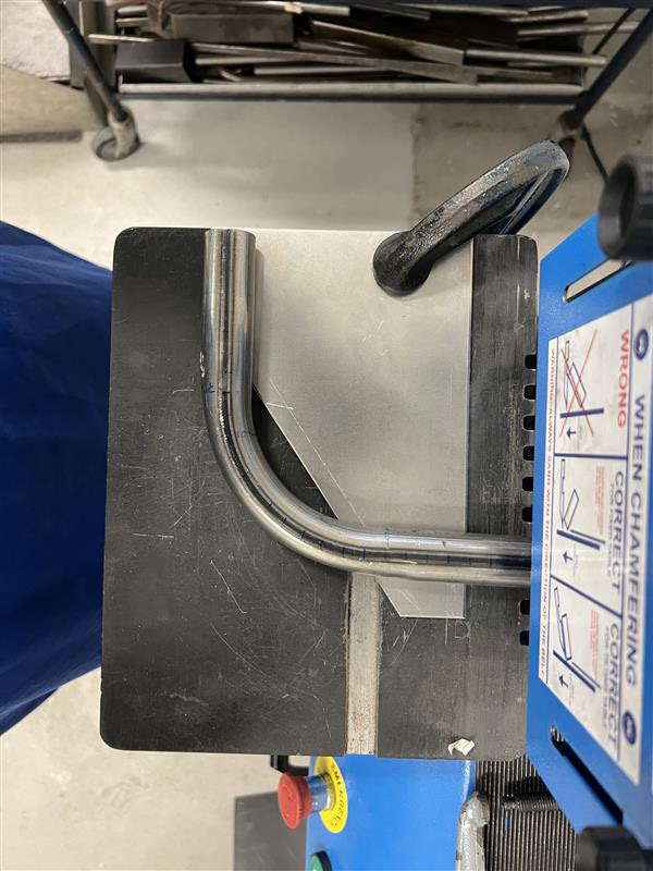
I knew the first thing I had to get right was perfecting the corners. This meant a bit of trial and error using the tube bender until I could consistently get perfect 90-degree bends with as little warping as possible.
I wrote a set of step-by-step instructions so I would not forget key aspects of using this machinery when going back to using this process in the manufacturing of my final pieces, or even further in the future when I'm working on different projects.
Step-by-Step
Using the tube bender requires a few steps to set up and achieve your desired outcome. There are a few things you will need before starting the actual process.
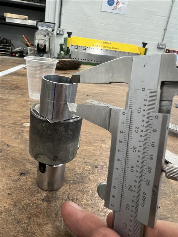
- First of all, all your PPE is required for all workshop tasks. You will then need to find the tube size you want to bend (do this by measuring the diameter with vernier-gate callipers), you then need to find a matching die for the machine which will hold your selected tube size in place.
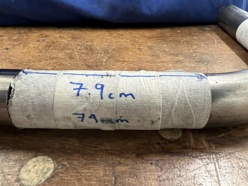
- You then need to measure and mark the lengths and areas you want to bend, taking into consideration that the tube will warp during the process.
- To set your tube in place, you position it between the dies and lock it in with the vice handle on the side of the machine, you then use a g-clamp to hold the front end of the tube in place. If your tube is excessively long you may need something to prop it up so the machine hasn't got 2+ meters of tube hanging from the other side. Make sure whilst you are setting up the machine that you make sure it is set at the angle you want (usually start at 0 degrees).
- Once set up you can start the bending process. Use the handles or levers of the tube bender to start the bending process. Apply steady, even pressure to begin the bend gradually. Pause periodically to check the progress against your markings, sometimes the tension in the tube will cause it to bounce back when the vice is released so check this before completely removing the tube.
- This process is best done gradually with pauses between to check the bend and see if the vice needs tightening or loosening to prevent the tube from warping too much.
Alongside using the tube bender I needed to cut each piece down to a more reasonable size as I was bending a big 3m lengths of the tube. This was to save on wasting material because I wasn't sure about how long to cut each piece before bending it. Using the horizontal bandsaw I could cut the corners from the other straight lengths of tubing that were left after using the tube bender. This machinery is a pretty simple process as it is mechanically automated and just takes a few steps to set up to get your desired cut (angle of cut, Size of material, etc.)
I wrote another set of instructions just as documentation for future projects and my own personal use.
Horizontal Band Saw
This bandsaw is a great piece of equipment. It allows you to get perfectly straight cuts at most angles. You have to be clever with how to do opposite-angle cuts but for this project, I am just cutting parallel lines across circular tubing.
- You can set the distance with a rig that was set up by the technicians but if you don't have this make sure to measure and mark all your cuts. The laser shows you exactly where it will be cutting so make sure you adjust it if it's not on your marks.
- As the saw uses a liquid coolant when it's on, you need to make sure you have a blue roll or paper towels to hand to prevent the liquid from dripping over the edge of the machine onto the floor as it would cause a slip hazard. Also, watch for when you remove your work as it will drip from the piece. You need to make sure your work is fully dry before moving on as a lot of metals will rust and as I'm using steel it is prone to rust if it's not dried. Your work will also have burs on the edge it was cut so make sure you have gloves on and are careful when drying and handling the metal.
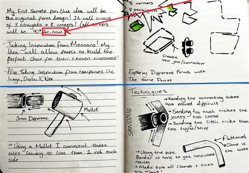
It was around this point I had finally decided on a final design. I was over-excited after doing more research on brands like Lego and Meccano as I believed I had a very original idea which could be a hit (as you can see from the image on the left where I was highlighting the opportunities my idea presents).
I then proceeded to use the time I had wisely and get my first sample put together as soon as possible. I used the same end-to-end tube connection process as seen in my samples for uc1. To do this I used primarily hand tools like mallets, files and sandpaper.
As all the tubes we have available are 1.5mm thick the diameter for the smaller tube will have to be 3mm smaller than the main exterior tubing. Using a mallet I hammered the smaller tubes directly into the exterior components (the large tubes), as each tube has a welding seam running along the inside left from the manufacturing process, it holds the tubes firmly together.
At this point, I wasn't aware that doing each batch, one process at a time, is a much more efficient way of working instead of completely refining one component at a time. This is what I was doing during my sampling stage however I wasn't perfecting each edge because I wanted to complete my first sample to get an idea of how long the final piece would cost me, take me, and get an idea of the scale of the piece.
Sample Vol. 1
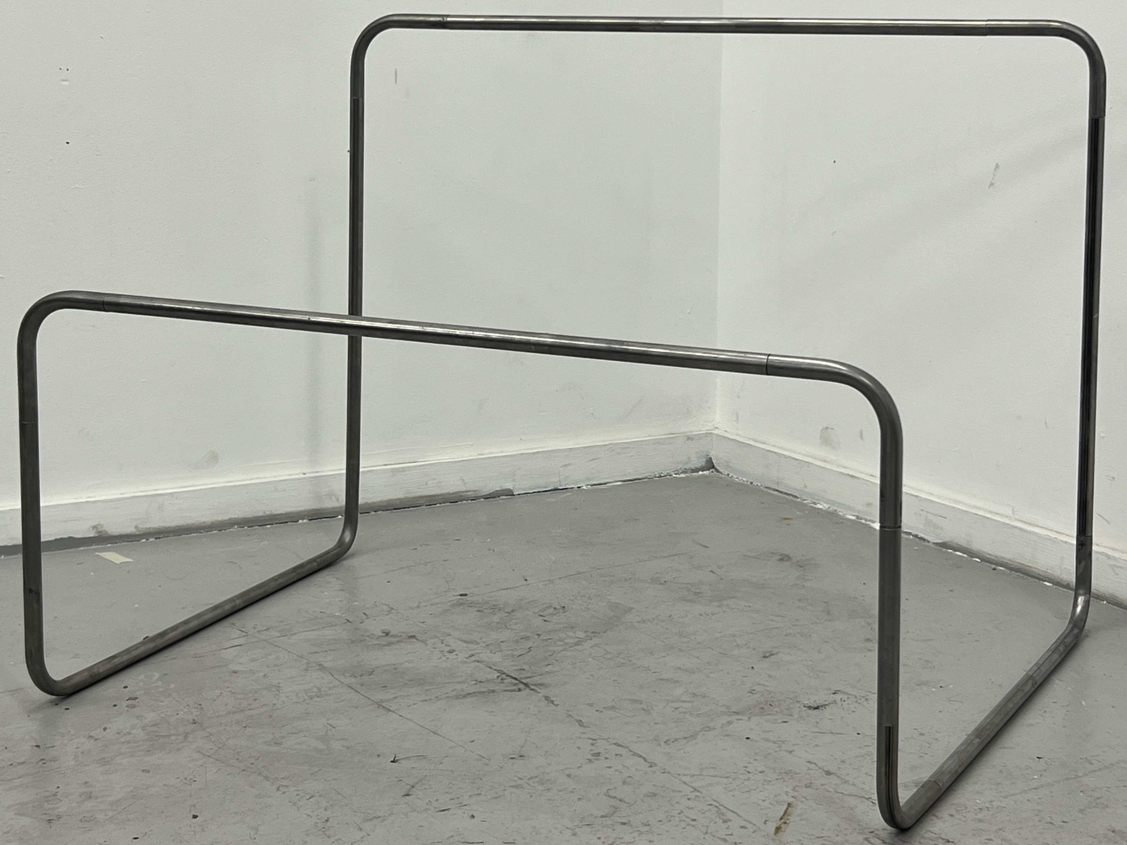
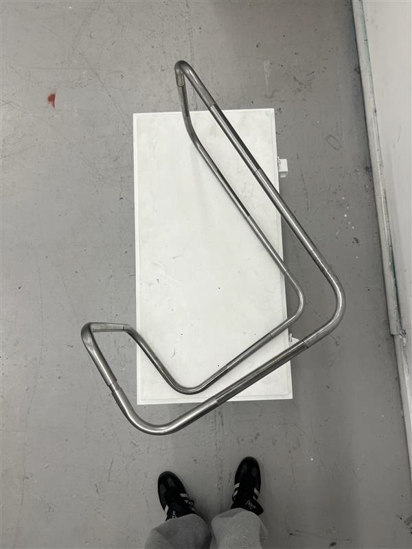
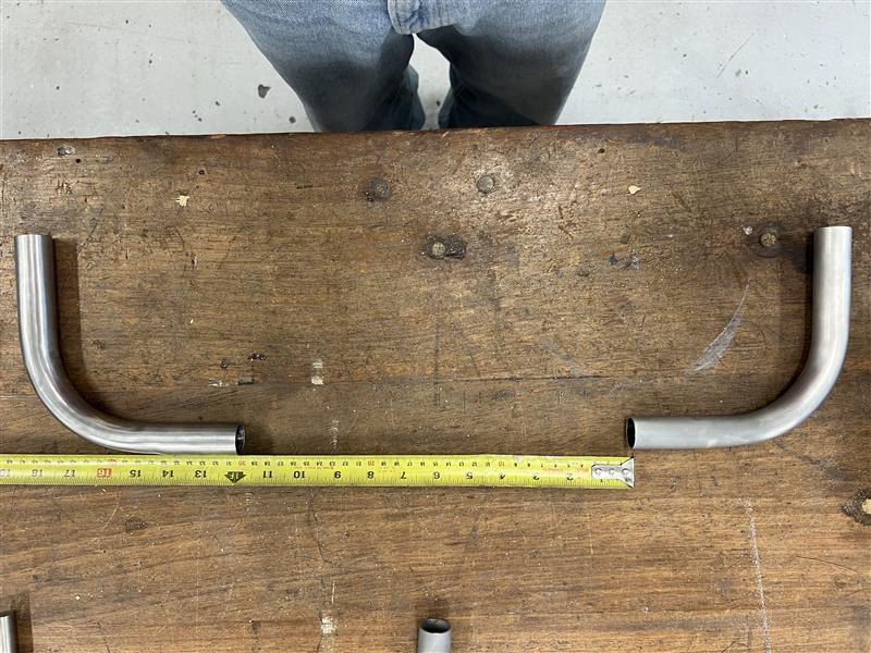
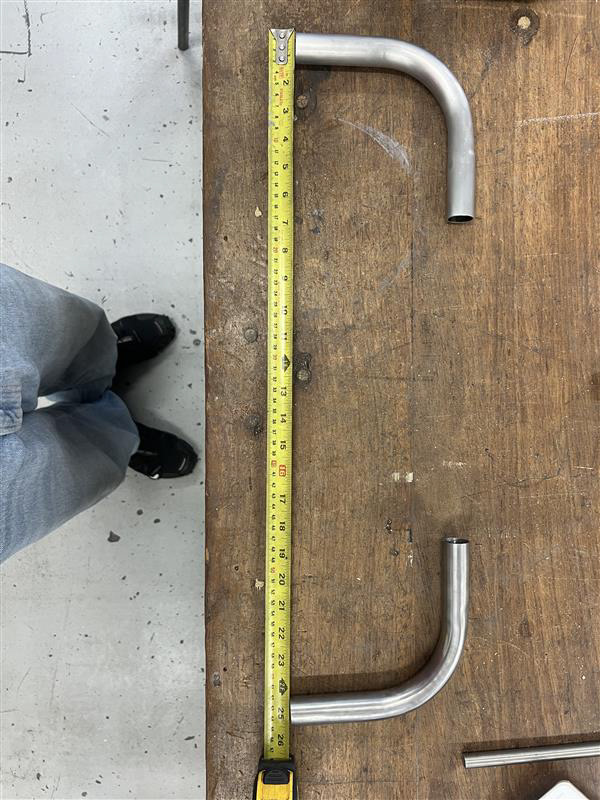
The outcome of my first sample was much bigger than expected. I do not know if this is because I may have rushed the measuring process of each straight, or because I was unsure of the standard size for chairs. Despite my overestimation of the scale of this piece, it still came out well and showed me that my form would come together and hold by just using the process of filing and sanding the tube until I get that firm fit that comes apart with some tension.
This sample highlighted a few problems that this chair had. However, it allowed me to go back to the drawing board and document what went wrong with this sample and what needs improving before moving on to the final piece.
Firstly and obviously was the scale. The thin 19mm diameter tubing paired with the large scale of this form was very out of proportion. I knew that my final piece would be made with thicker 1-inch tubing. I also knew I needed to do more primary research on the size and scale of chairs which I documented in my research.
The next biggest problem was not refining and recording the angles and lengths of each corner component. This was a big problem which left my sample very wonky, and I believed it only went together due to the excessive lengths of the straight components.
Another issue that I've highlighted, is that not all of the connections were smooth. Some were very loose and would fall apart when moving this piece. Some of the connections were far too tight and ended up getting stuck, which affected the modular aspect of my design as it wasn't able to be fully disassembled.
The final aspect of this sample that I documented was how much of a gap was left between each connection. This defeated the seamless aesthetic and was due to poor filing or angled cuts from cutting the edges. This wasn't fixable, once the male connections were attached so I made sure to remember to refine this first for my final piece.
The next stage in my design process was altering and fixing my initial sample. The first problem we discussed, was the overall size of the form which I wanted to reduce. This first form wasn't a practical size to show in critical analysis sessions so this seemed to be the best direction to head in at this stage in my project.
At this point, I also wasn't sure if my design had complete creative freedom, which was a huge aspect I wanted to achieve! The idea behind my piece is based on modularity so I wanted to give the piece more freedom for the consumers so they could be a part of the making process and inspire me and others with their creations.
Due to not refining all the connections I wasn't able to disassemble every piece into individual components. Some came apart with ease, but some wouldn't budge as I didn't spend enough time filing and sanding the connections. This meant I could only refine the scale of my initial sample instead of also fixing the connections.
Here is a video showcasing me putting all the components together after shortening each straight length. This video is the perfect demonstration of how the pieces will go together and come apart, despite the slight struggles seen as these unrefined sample parts wouldn't come apart easily.
This process of building the form with each component displays the fun and enjoyment I want every customer to enjoy. I posted this video and exclaimed that I felt like a young kid playing with Lego on my bedroom floor. This was a very nostalgic moment which I wish to share with customers who buy this product.
Throughout a lot of these making processes, I have been recording and posting them across social media. Videos like this have got lots of traction and show that people like to see people and processes behind final designs. I thought that sharing these videos on Instagram and TikTok would be beneficial for this project as UC2 revolves around your future and the next steps in your design and craft career, and starting to build an online portfolio seemed to go hand in hand with this project.
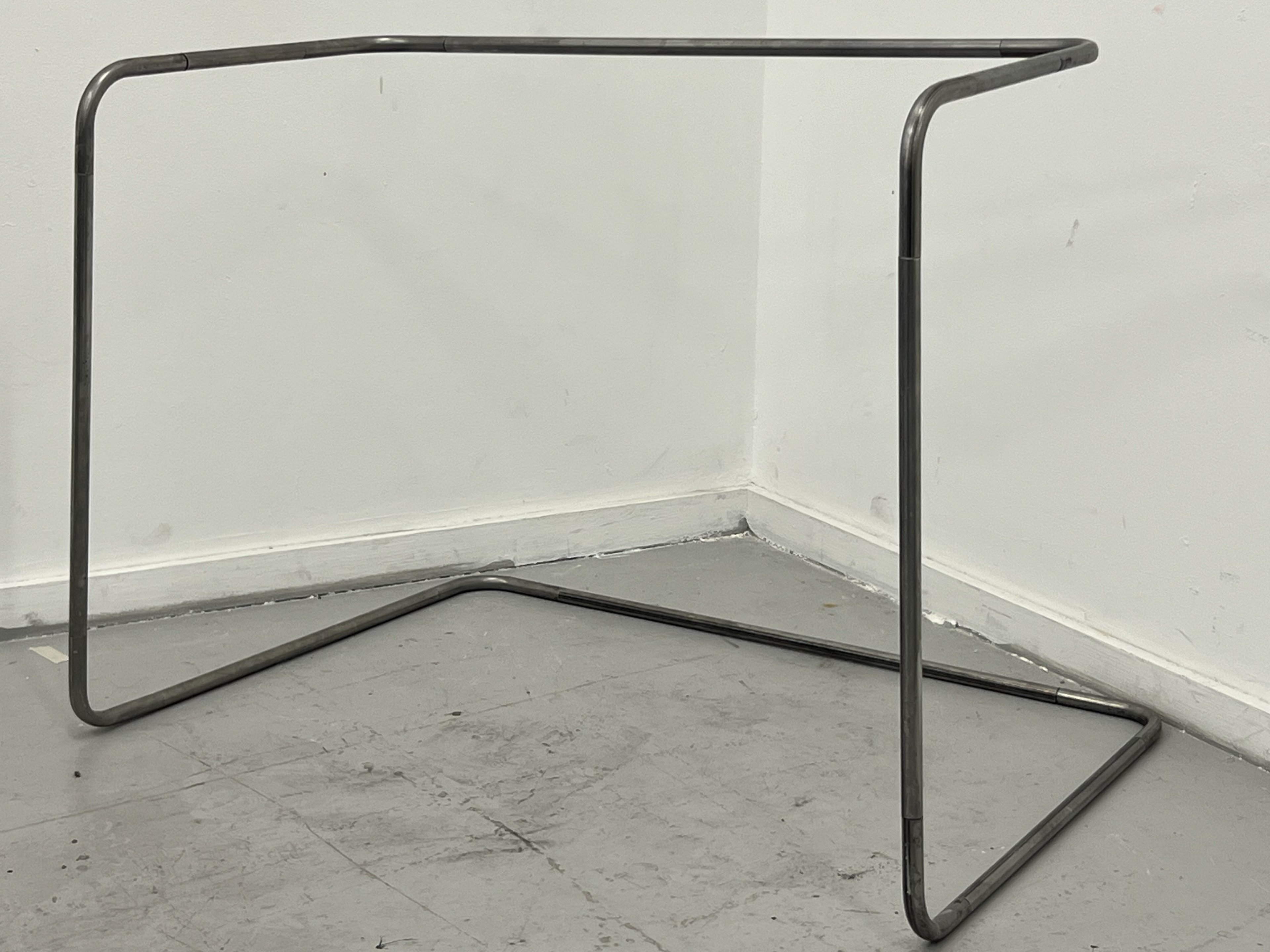
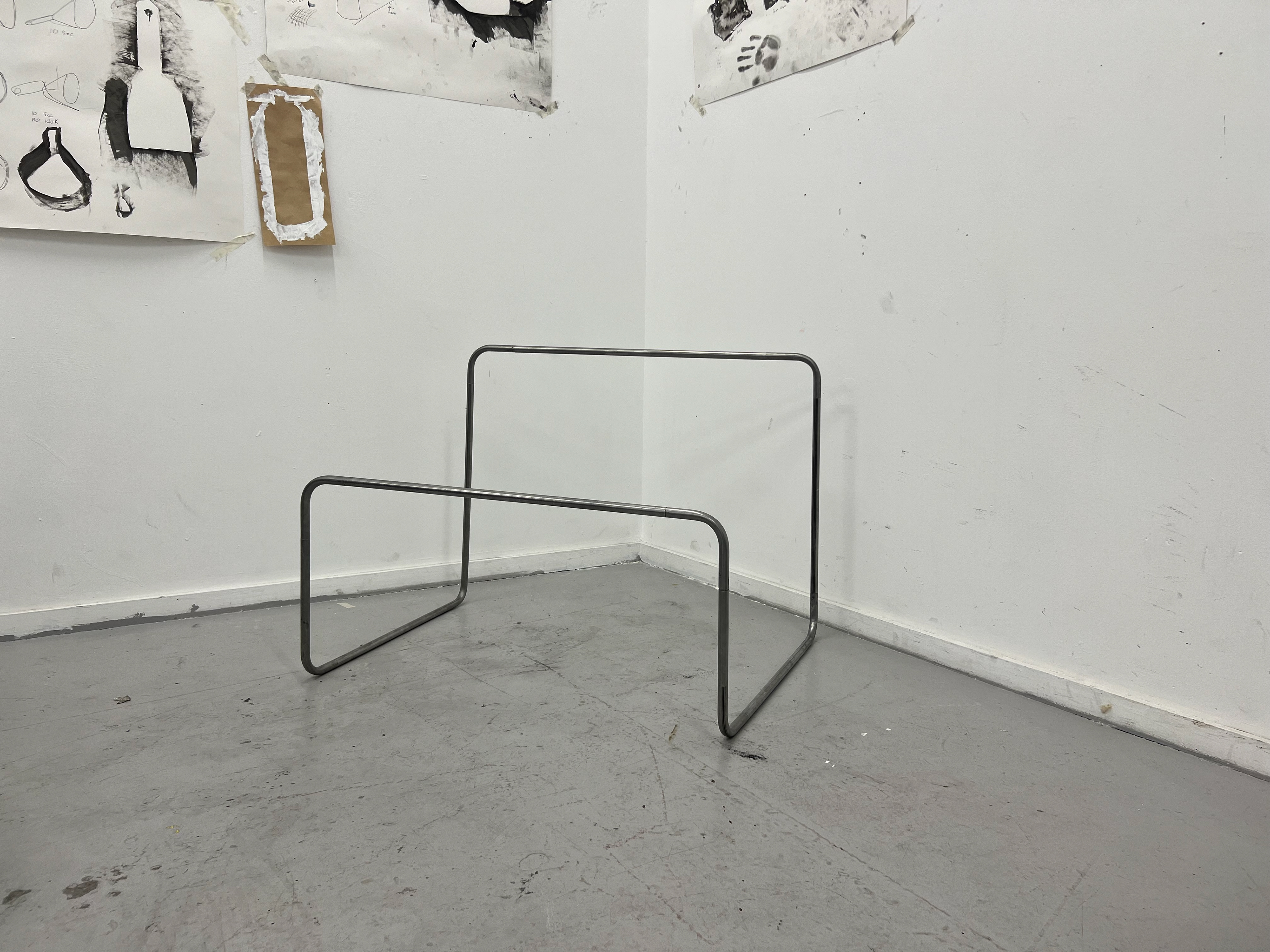
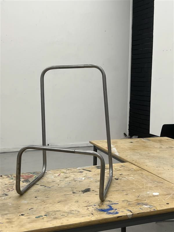
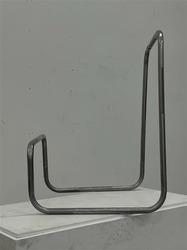
The images below are the outcomes I achieved for my second sample piece. It was a little wonky and a lot smaller but was a much more workable size for a sample. I could display this on the table to showcase it to lectures and also tuck it away much easier. I also think creating this sample at 2 different scales, shows my idea of modularity and adjustable size and scales.
Sample Vol.2
I got some more video content of my samples! this was primarily social media content, however, I think it is also good documentation for my portfolio. Here are the original clips but you can see my edited reels here.

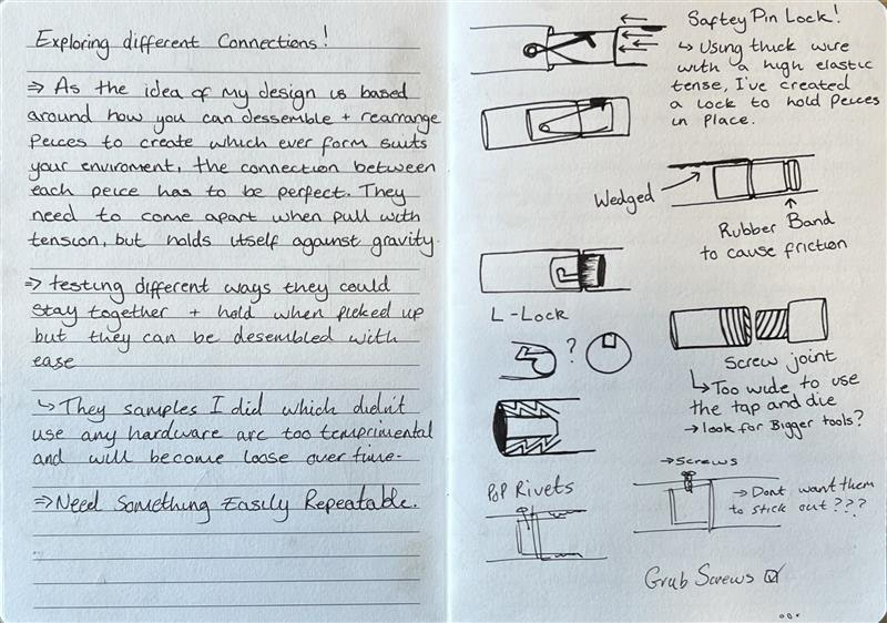
Once I had finished my samples of form, I took it back to the drawing board again and drew out everything I needed to refine when making my final piece. I had thought about different joints and connections to hold the components together. I still wanted it to be seamless so I didn't want to use external connecting pieces. I spoke to the technician (Paul) and he suggested that some of my ideas would and some wouldn't work. He told me some of the design flaws with these ideas and suggested how I could make some of these work and why others wouldn't. I decided to sample some of these ideas before jumping into my final design and not knowing which connection I was going to use.
Design Update!
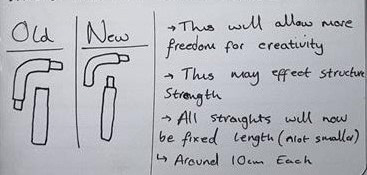
After further tests, samples, and research, I discovered the idea of how to allow more creative freedom. This idea would mean standardising all of the components including the straight lengths which will vary depending on where they go. For example, the height of the front of the chair may have no straight pieces at all and could be connected with the 2 corners, and the height of the back could use 3 or 4 straights all of a standardised size so you can build the chair however big or small as you please. Not only was I making all the straight components equally smaller I also changed the original idea of connections. My original design and my samples showed that each corner piece would have 2 male connections and all the straight would have female connections on both sides. After more thought this idea didn't make sense as it limits what can be connected where! I decided to change it so each component would now have 1 male and 1 female connection which would allow you to connect whichever pieces you like together allowing complete creative freedom!
The one problem I have found with this idea is the seat itself. I wasn't at first sure how I'd make it as flexible as the frame so I looked back at the other brands I had researched and had the idea that when you buy this chair you're buying that idea too. However, it doesn't stop you from buying 2 sets and joining them together, just like Lego sets. This also would require a set of instructions so it was at this point I started to research how Ikea shows clear instructions on how you piece together their furniture.
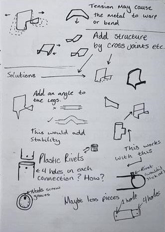
standardising these components doesn't just allow for full customisation, it also solves some problems I've had with the triangulation of the piece. It will allow me to add pieces wherever to increase the structure of the frame, I was told that 2 parallel feet for the chair would risk it warping durastically so by changing the design of each component i can add corners into the base of the chair to make sure it
Old
New
Making My Final Piece!
Even though I put together a pretty sturdy sample in only a few weeks I knew making my final piece with exceptional craftsmanship would take alot more time and patience. Through this part of my making
I knew I didn't have alot of time and I knew exactly what I was going to make so without wasting any time I proceeded to the first step in the workshop which was creating the corner pieces!
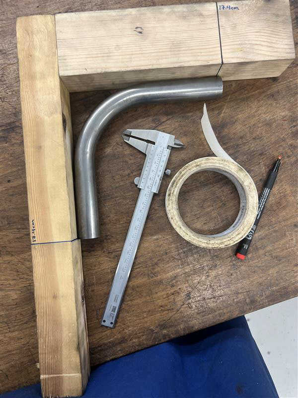
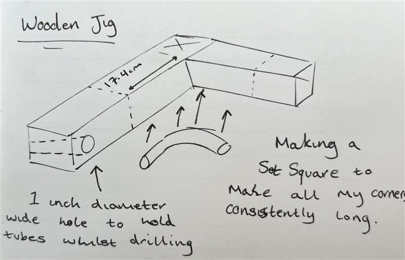
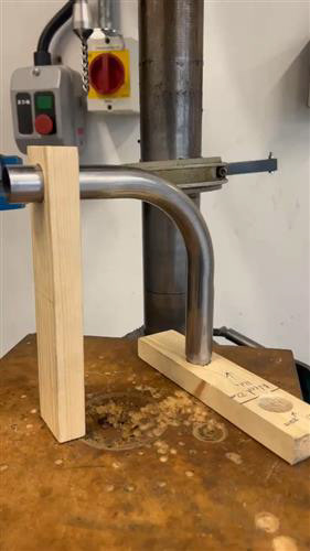
Firstly, I set out to make a jig. This was so I could measure and check each connection to see if I had bent them too little or too much. I made this jig out of scrap wooden blocks and I first checked if the edges were completely flat otherwise I would be using a wonky tool to measure all my components. Once I knew they were flat I measured where the two blocks would be connected and marked out a couple of lines so I knew where to drill. I drilled some deep holes, all the way through one block and just short of an inch into the other. I had drilled these holes so that I could screw the in easily knowing that the wood wasn't going to split. I used several tools to make sure the process was right including rules, set squares, clamps, and more to make sure that the jig was perfectly accurate. I was basically making a big set square so I could see if the straight edges coming away from the bend would both touch and stay parallel to the jig. This also allowed me to measure how much was left straight from the front end of the bend and standardise that length on both sides to save time cutting and sanding both ends. I understand that this process sounds complicated but it makes more sense when looking at these images and also shown in this video.

I had already practised this process so I was very familiar with the machine but I needed to make sure every corner was perfectly 90 degrees and had equal lengths on both sides. This narrated video explains each step to make sure this process is consistent for each component.
Once I had the jig made it was time to just rinse and repeat this process taking my time on each one bending it and then measuring it little by little until they were perfect. Some corners surpassed the 90-degree mark and I fixed these by clamping them into a vice between some cloth and using my hands, pulling the bend back on itself before putting it back into the tube bender again to see if I could fix it. I only had to do this 2 or 3 times where I only had to scrap one because I had bent it back and forth too much I was worried the metal had become weak.
I set out to make 12 of these perfect corners even though my original form only used 8. I wanted to make enough to see if some of my other forms would work and I also wanted to make more than I needed to ensure I have spares if one of the processes goes wrong later down the line.
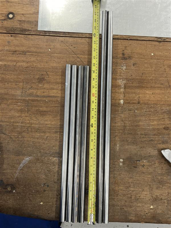
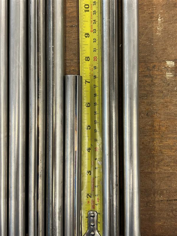
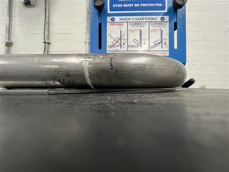
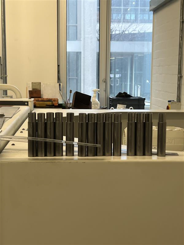
I then moved on to creating the straight components. I had already decided that I wanted each piece to be 10cm long so from here it was a very straightforward process.
I took another 3-meter length of tubing and set the bandsaw up to leave me with 10cm lengths. The only thing you have to be care Cutting all these pieces only took me about 10 minutes which you can see a small sped-up clip of here. However, the next process of filing and sanding all the cut edges took hours as I was left with 30 straight components and 12 corner components.
Now I was on to the tedious process of filing and sanding these edges the first step of this process was de-burring each edge. I made a couple of videos, the first describes the technique of de-burring the sharp edges to prepare the components for the belt sander. The reason we do this process before using the belt sander is to protect me from cutting my hands as you cannot wear gloves on the belt sander and also to prevent the sharp edges from damaging the machine and ripping the sandpaper.

After meticulously hand-filling all the sharp edges It was time to perfect them edges even more. To do this I started sanding each edge with different grit sandpaper, I used a sanding board with a clamp holding the sandpaper to the board and the board to the table, this would prevent the sandpaper from moving during the process. The technique behind this process is performing figure eight motions keeping the whole surface touching the paper flat. This was an ARM workout. I could see after doing the first few pieces, this would take a very long time.
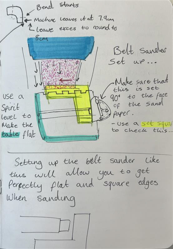
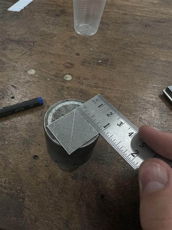
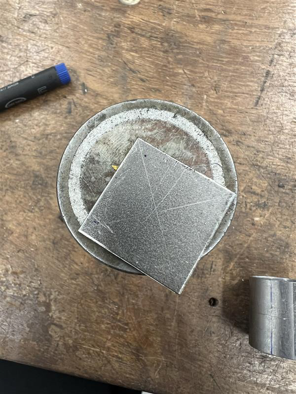
I then resorted to the belt sander. This sped up this process drastically and still gave me the desired outcome. It wasn't immediately straightforward to start this process though. I had to make sure I set up the machine properly and looked at the possibility of making a jig to make the outcome more accurate and consistent. I had looked at this idea when sampling and saw that the middle of the curve on the corner components pushes out more than the original 25mm diameter of the standard tube. I tried making a 3mm thick steel triangle to put under the tubes, this fixed the problem I had with my sample but I found when doing this for my final components my corner pieces were better made and didn't have this issue so using that jig was not necessary.
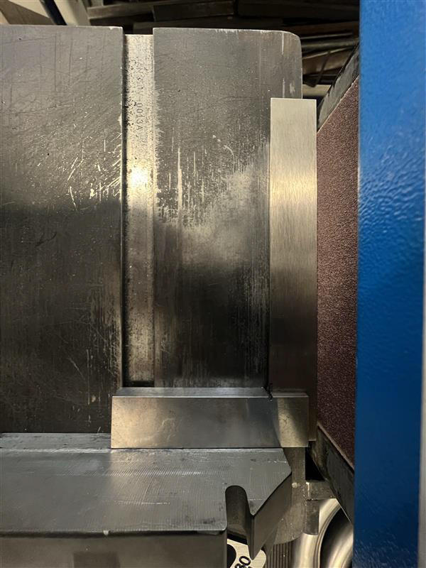
The few things I needed to make sure that was right on the belt sander was that it was level, surprisingly to do this I just used a spirit level, a straightforward process of making sure the bubble sits between the two lines meaning the surface is level.
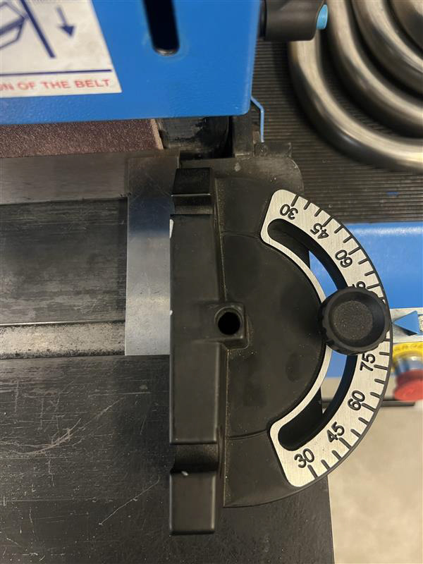
I also had to make sure the adjustable mitre gauge was 90 straight to the surface of the sandpaper. I did this by placing a set square against the edge of the sandpaper and making sure the mitre gauge was loose so it would line up to the other side of the set square before tightening it so it would stay in place.
These steps are all very straightforward forward but making sure they're right is crucial. the actual processing of sanding is also very simple, you just need to make sure that you keep using the mitre gauge to push the piece instead of pushing against the gauge, this video explains what not to do when using this machinenry in the way ive demonstrated.

The next stages in my making process were the most challenging and time-consuming. This consists of making lots of jigs to make all the holes as accurate as possible.
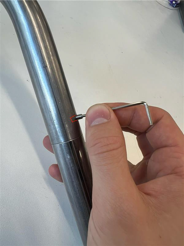
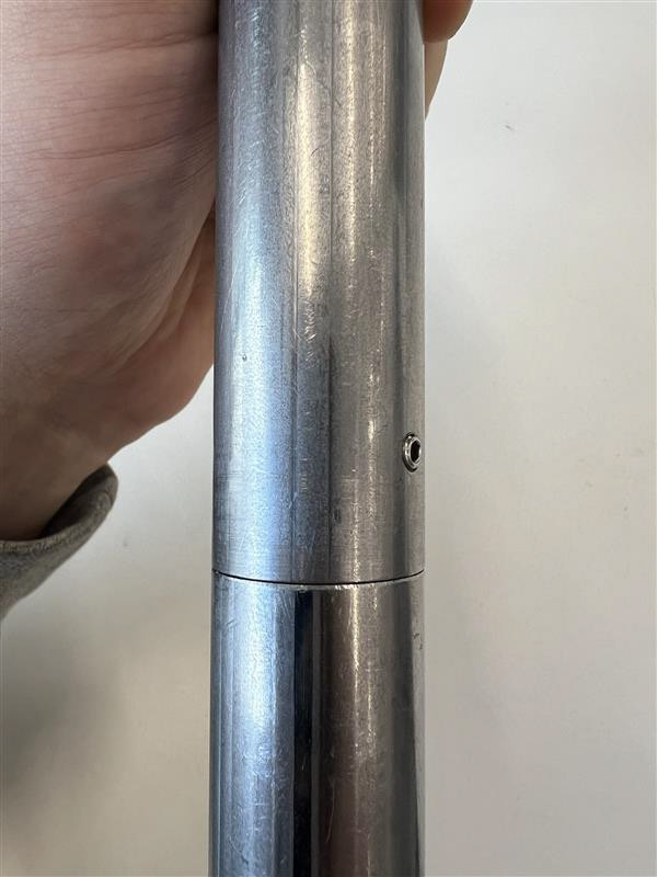
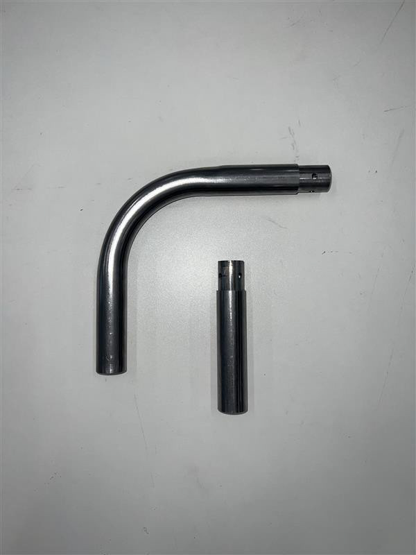
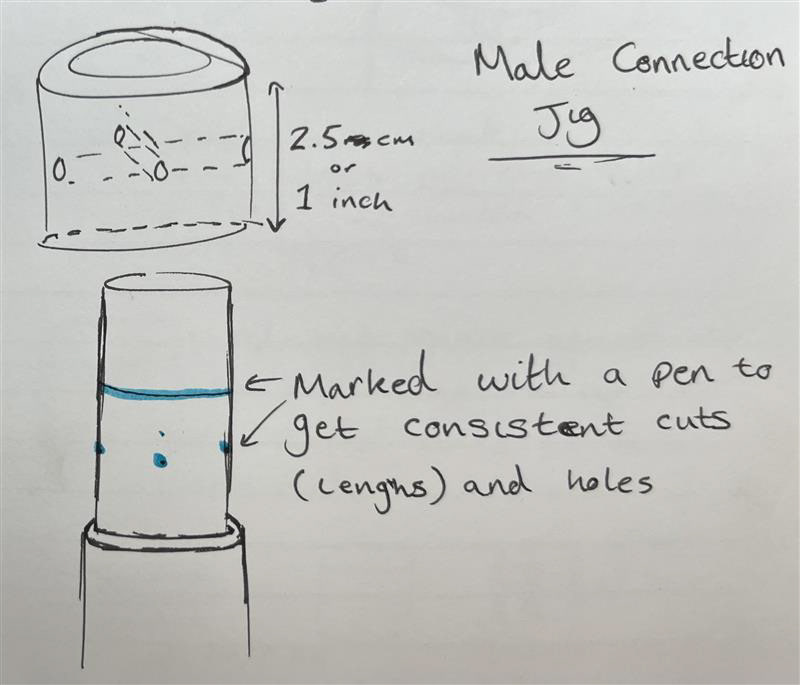
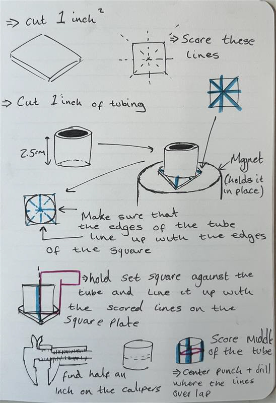
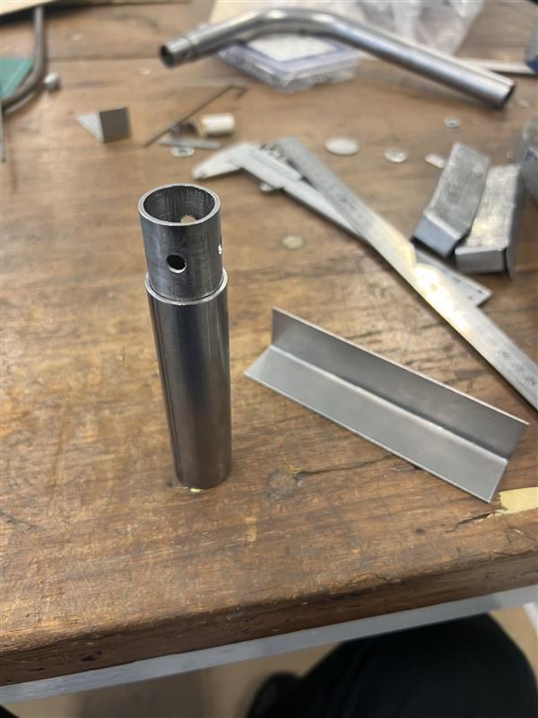
The first jig we made was for the 4 holes on the male connection which would sit on the interior tube. As I had decided to use M5 grub screws I thought to make these holes 5.5mm wide. This would allow room for the grub screw to sit in however it would not thread on this piece of metal. I wanted all the holes to be on 2 opposing axis, meaning they are each equally a quarter distance around the circumference of the tube axes. The images and my diagram explain how I went about making this jig which I then used to make a dot on each component.
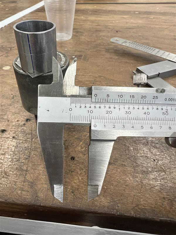
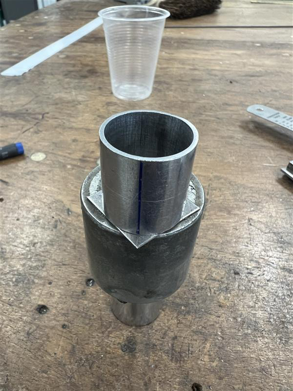
For this process, I had to do one piece at a time as when I inserted the 22mm tube into the 25mm I marked and Cut each piece individually. This took more time but saved in material costs as I could measure how much I needed to cut off at the same time as marking the holes.
For the corner components, it was a bit more difficult as I wanted each piece to line up with the bend. Meaning one hole was perfectly center with inside of the curve and another with the outside. To get around this problem I used a set square and carefully knocked the jig around until I looked as accurate as possible.
Once I had all the male connections in each component looked like it was coming together. I had all the pieces marked and centre punched so the next process of drilling the holes was easier.
I did not get any picture or video of me drilling these interior holes but it consisted of clamping and adjusting the jigs to the table of the pillar drill and until each centre punch mark lined up with the drill bit.
After all the holes were drilled It was back to filling and sanding the burrs from the edge of the male connection. This followed all the same processes as before so i wont cover it again.
By this point, I wasn't confident about the next stage as I wasn't super happy with the outcome of my interior holes. They were entirely accurate and I didn't think that the grub screw idea would work. I thought a good way to spend this time would be to use the Dremmel to take out the welding seams on the interior of each tube. This would allow each piece to slot together and I would then be able to start building forms before deciding on how to fasten them together. Yet again it was another very simple and tedious task.
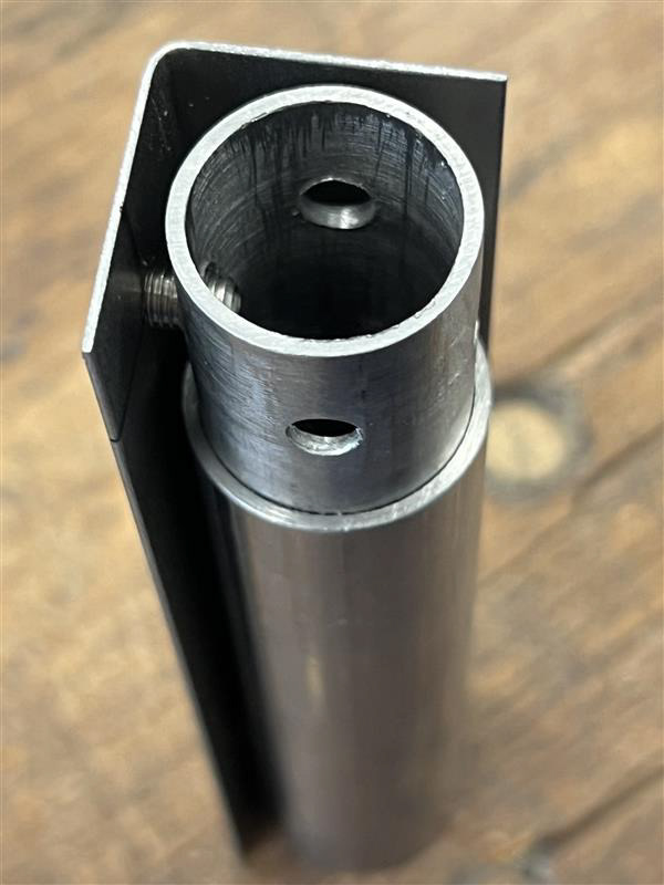
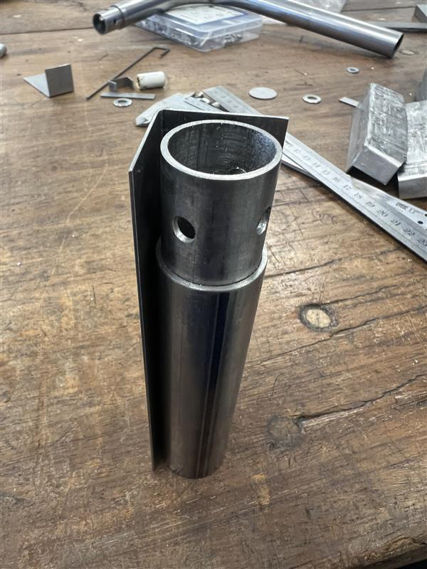
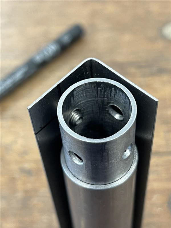
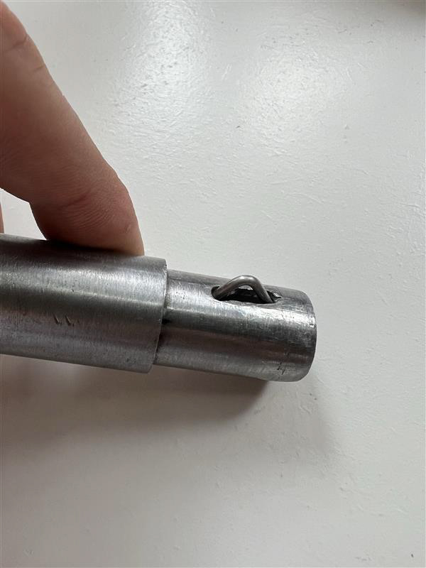
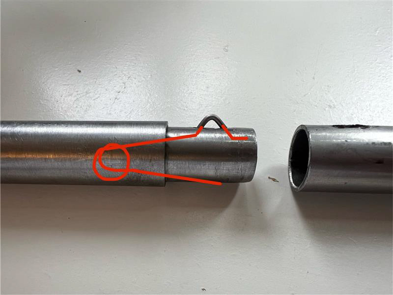
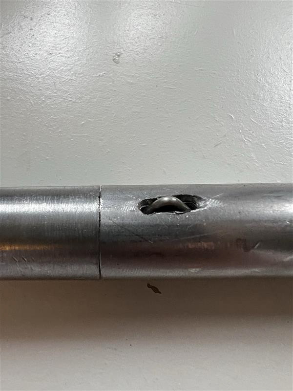
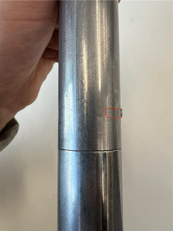
I overcame this lack of confidence and made myself a jig to mark where I would drill for the exterior holes. I made the jig by finding a scrap piece of sheet steel and making sure it was 2 inches wide and 12.5cm tall, this was so I could bend it down the middle and it would allow the tube to sit in the bend nicely. The picture explains this process better. I then could draw and mark an even line to drill 2 holes making the interior holes be on the same axis as the exterior holes. I was surprised with how well this jig worked and was so happy that I followed through with this process as I was almost going to leave it. This risk paid off, allowing me to lock my pieces together as I liked.
The next and final stage of my making process was the Tap and die the holes for the screws to fit in nicely. This was carefully and simply applied the right amount of pressure onto the drilled holes and turn it slowly whilst making sure you are completely above the hole meaning the thread wont be wonky.
Making the Seat
Making the seat came with learning new skills. Crafting with fabrics is something I haven't done in a very long time. I managed to get myself inducted on the sewing machines from the Make-More store so now I just needed to figure out how much fabric I needed and how tort I wanted to make the seat.
I assembled the main seat I wanted to hand in and used a piece of string to measure how tort/loose I wanted the fabric to sit on the frame. I measured about 120cm long including measurements for the loops around each edge of the frame. I then measured the length of the width of my chair which was 3 straight components and 2 corner components. For the width I got 50cm this also included room for hemming the edges.
I took my time and pinned the fabric up onto the chair to see if it was the correct size after pinning the edges for hemming it looked pretty perfect. I have a video of me sewing this piece here. I would've imported it however the video size was too large as there are multiple clips on this video.


